Welcome to Laser Pointer Forums - discuss green laser pointers, blue laser pointers, and all types of lasers

Buy Site Supporter Role (remove some ads) | LPF Donations

Links below open in new window

FrozenGate by Avery

LMS1587 based linear driver

Joined
Feb 9, 2011
Messages
578
Points
0
LMS1587 - 3A low dropout fast response regulator
data sheet *here*

I been browsing around for a possible new driver. Looking at the data sheet it looks promising. It's similar to the LM 317 but with a higher amp rating and lower voltage drop. Am I right or wrong? Any thoughts about this? :can:

I am interested in making a build for this, but before I do I wanted some feedback from people here if it's worth it.
 
Last edited:


The larger size may be a factor.

3 Amp current rating is nice if you need a lot of current.

LarryDFW
 
The bigger the better! :D Well, power/current wise but then again it depends?:thinking: Oh man I think I should stop for tonight :tired:. It's only a couple millimeters larger than the LM1117 but I think it's because the LM1117 is a TO-252 package and the LMS1587 is a TO-263 package.
 
They have fixed versions for 1.5V and 3.3V, but they also have an ajustable version for 1.25V-5.7V.

Would that pose a problem considering the limited adjustable voltage range?

I might just bite the bullet and go ahead and build one just to see it's capabilites. Or use PSPICE for DC simulation?
 
this should work, it can be used as direct replacement for LM317 (it has the same pinout)
they're offering multiple regulators with fixed Vout and also regulator with adjustable Vout, both in 3A and 5A Iout versions
any1 knows where to order it/get free samples?
 
Last edited:
You can buy them on Digikey or probably eBay. I think I might go ahead and try this but it'll take me some time since I'm swamped with school right now. Also, the place where I get my PCB takes about a week or so for them to make the prototype board I'll be using.
 
Jufran:
Did you end up ordering any? If so, I'd be really interested to hear your feedback.
If not, take a look at the 1085 and 1084 regulators. They work great as direct replacements for the Lm317 as long as you have good input/output caps, and are fairly cheap (~$2 each) The dropout is around 1V depending on current.

I've just spent a half hour or so reading up on this:
Digi-Key - 576-2231-ND (Manufacturer - MIC29312WT)

It's not a direct pin-compatible replacement, having 5 pins instead of 3. However, one of those pins (the enable) can just be tied to the input pin. The other is GND, which shouldn't be a problem to add for most driver setups.

The benefit ?
At 1A current, the dropout is 0.25 V, and at 2A current it's ~0.38V
Pretty nice :)
 
@rhd:
Oh, that looks nice! I like the specs on that. :) Did you already build one yet? I might be tempted to make one using this chip in the future! :beer:

I haven't ordered any pieces yet, but I'm building a prototype PCB and it's almost complete. I was planning on using these in my future builds. I'll be sure to post my feedback when everything arrives!
 
Careful with input voltages, anyway ..... absolute maximum Vin 13V, normal maximum Vin 12V.
 
The 1085 yes - I've done a bunch of builds with it. Easy as pie to use.

The one referenced above - the new really low drop out ic I found- haven't tried that yet. If someone else will give the datasheet a quick glance and thumbs up, ill order some and give it a shot.
 
The one referenced above - the new really low drop out ic I found- haven't tried that yet. If someone else will give the datasheet a quick glance and thumbs up, ill order some and give it a shot.

The Micrel 29312 Chip looks good to me.
The Vin(Max) is +16v with an absolute max of +20v.
Vref = 1.215-1.265 (Basically 1.25 like the LM317)
Dropout is way lower.


I'll add a couple to my digikey order for testing as well.
 
Do you suppose 10uF ceramic caps on the input and output would be sufficient ?

I need to place a digikey order again too, so I will do so also. I ordered from Mouser last week, and it still hasn't arrived. What a mistake.

Actually, while I'm at it - do you have a digikey favorite resistor around ~0.75, 0.8, 0.9, etc Ohms, for current setting? If not - don't search for one - just thought you might know of something off hand that was a decent power rating & small.
 
The datasheet shows a larger (22uF) cap on the output, but a 10uF should be fine on input.
I don't know of resistors offhand, but I will need to order some as well.

Edit: Missed the point, yes 10uF is probably fine, I'll use a 22uF because I have it in inventory.
 
Last edited:
I say go for it! :beer:

@rhd:
a 10uF capacitor should be sufficient for our laser diodes. It's just to keep any voltage spike from destroying the diode. That IC looks pretty efficient to me. Try using 2512 package resistors since they can handle up to 2W. Digikey usually has a better selection of surface mount resistors than mouser from my experience.

@HIMNL9:
Unfortunately the LMS1587 maxes out at 13V :(, but it should be ok for any diode. I don't think we would need more than 12V to power a handheld.
 
Ok, so I finally finished my design. However, I need some feed back before I send it to the boardhouse. The deadline is March 28 and I should have the prototypes by April 10.

Low drop out regulators have the advantage of having a lower minimum operating voltage, higher efficiency, and lower heat dissipation.

My design is a TO-263-3 package and can be interchangeable with different LDO regulators as long as the package size is the same. There is a diode for reverse polarity protection and 2 10uF capacitors required for the circuit. The resistor pad sizes are 2512 for interchangeability if higher currents are desired and rated up to 2W. Probably a max of 1.6A for 2W resistors. However, if you have (2) 2W resistors in parallel should be able to dissipate 4W? The max current for this specific IC is 3A. There is another IC rated for 5A, but sold in canada which makes it more expensive for shipping :cryyy:

Here is my schematic:
attachment.php


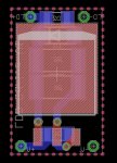
And the board:
attachment.php


Let me know what you guys think :beer:

EDIT*: I should have connect the negative to ground to make routing the traces easier :whistle:
Will update later today before I submit my design.

EDIT:

Updated schematic:
attachment.php


Updated board:
attachment.php
 

Attachments

  • LMS1587layout.jpg
    LMS1587layout.jpg
    126.4 KB · Views: 712
  • LMS1587Schematic.jpg
    LMS1587Schematic.jpg
    24.4 KB · Views: 823
Last edited:


Back
Top