
Welcome to Laser Pointer Forums - discuss green laser pointers, blue laser pointers, and all types of lasers
How to Register on LPF | LPF Donations

Navigation
Install the app
How to install the app on iOS
Follow along with the video below to see how to install our site as a web app on your home screen.
Note: This feature may not be available in some browsers.
More options
You are using an out of date browser. It may not display this or other websites correctly.
You should upgrade or use an alternative browser.
You should upgrade or use an alternative browser.


- Joined
- Dec 18, 2010
- Messages
- 6
- Points
- 0
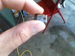
Alright new development and a new problem. So I got both pwm circuits working perfectly (diode included pointing at positive) but when I tryed to fire up with the larger motor it worked for about 10 seconds and then the mosfet burned up. I was trying various resistors to attain the voltage I wanted at the motor but they either burned up or didnt really make it turn so I just connected the motor to test. any suggestions?
Attachments
HIMNL9
0
- Joined
- May 26, 2009
- Messages
- 5,318
- Points
- 0
What mosfets are you using ? ..... you need low voltage high current mosfets, like IRF4905 or similars (anyway, at least 10 times the current rated for the motor current in free-running, cause under load the current of the motor increase a lot) ..... NOT high voltage mosfets, that are usually rated for low currents .....
- Joined
- Dec 18, 2010
- Messages
- 6
- Points
- 0
Im currently using IRF510's on this build. I figured that they were the right choice but im not entirely sure.
HIMNL9
0
- Joined
- May 26, 2009
- Messages
- 5,318
- Points
- 0
IRF510 ..... RdsON 0,6 ohm, current 4A ..... not the better one, but i think it had to resist, at least if your motor don't need to make a lot of efforts for turn ,,,,, BTW, what motor are you using, normal DC small motor with a demoltiplication gearbox ? ..... or something that requires high currents ?
Anyway, IRF510 still need to be heatsinked, imho, cause with 600 milliohm of RdsON, it will produce a lot of heat (600mW each A, may not look so much, but are 600mw/SECOND, after all) ..... and a DC motor can require much more current under effort than the one rated for free-running (i have small DC motors that are rated 500mA in free running, that are also rated 4,5A in max torque cycle and 14A in stopped rotor condition, ofcourse this burn the motor in minutes, if you power up it with blocked rotor, but the currents are these ones).
A more powerful mosfet will be much better, like as example these ones (and remember that less is the RdsON, less is the power turned in heat from the mosfet itself in ON condition):
IRF1010: 60V, 84A max, 12 milliohm RdsON
IRF1104: 40V, 100A max, 9 milliohm RdsON
IRF2805: 55V, 75A max, 4.7 milliohm RdsON
IRF1503: 30V, 75A max, 3.3 ohm RdsON
and so on ..... still need a heatsink, imho, but these ones have also enough current for work without blow up in seconds also without a heatsink (also if probably they will become hot).
Also, if you can access an oscilloscope, try to check the waveform that drive the mosfet ..... more the fronts (up and down part of the waveform) are vertical and "quick", and with no spikes, and better it is ..... remember that a PWM circuit dissipate more energy in heat in the rising and falling times of the waveform, than in the ON state, so, more they are quick and clean, and better it is.
- Joined
- Dec 18, 2010
- Messages
- 6
- Points
- 0
Alright after a little bit of work and some problems with balancing I present to you the led windmill. Thanks to everyone who helped me out with this.
http://www.youtube.com/watch?v=PHFkt8MwWME
http://www.youtube.com/watch?v=PHFkt8MwWME
Last edited:
- Joined
- Dec 28, 2010
- Messages
- 280
- Points
- 0
That is probably one of the coolest things I have ever seen a DIY'er make, you can definitely expect kipkay to copy this and call it a "led wood hack" or something.
Awesome job man!
:worthy:
Awesome job man!
:worthy:
toutan
0
- Joined
- Dec 1, 2010
- Messages
- 202
- Points
- 28
Beautiful
With those clumsy two left meathooks of his? Not in a 1000 years...., you can definitely expect kipkay to copy this
marcwolf
0
- Joined
- Jan 22, 2011
- Messages
- 4
- Points
- 3
Hi Folks.
First time here and I want to say how impressed I am with the orbs. They look fantastic.
Whilst reading the construction notes I could see similarities to issues I have with some of my projects (I do animatronics)
1. Communtators to transfer power. This is always an issue because you need something that will spin, as well as carry the power. I have found the 4 connector 2.5mm (and 3.5mm) video plugs and sockets great. You can use silicone grease for lubrication.
(Link here PRO SIGNAL|PSG01491|PLUG, 2.5MM JACK, 4POLE | Farnell United Kingdom PRO SIGNAL|MJ-069|SOCKET, 2.5MM JACK, 4POLE | Farnell United Kingdom )
That will give you 4 conductors. If you need more then put one at each end and use the motor with either gearing or a simple pulley and belt arrangement like in old cassette units, then you can have 8 links.
2. Easy solderable materials. I find that paper clips - straightened and then soldered gove a very strong result. Much stronger than standard component leads, plus they are very cheap. You can get a range of paper clip sizes and hence different thickness of wire.
Often I find that I need to control multiple LED's from a couple of wires. A 74HC154 is great because it can give you 4 to 16 lines to control the LED's (the 74HC138 is a 3 to 8, and the 74HC139 is a 2 to 4 decoder). As it has a Enable line on it you can use that for PWM and select the LED for lighting with the others Inputs. If you want to write some specialsed functions then use something like a PicAXE (which you can program in Basic) to give additional intelligence on the inner rings. You can work out your own communications but the PicAxe can handle serial, pulse length, IR, and A/D which gives you a lot of solutions.
Anyway - I'll keep looking around the site.
Take care.
Dave a.k.a. Marcwolf
Last edited:
D
Deleted member 8178
Guest
Guys
Guys, listen
I have the best idea
Guys listen
I have the best idea ever
Guys
I'll replace the LEDs
Guys
Replace the LEDs
I'll replace the LEDs
Guys listen here
I'll replace the LEDs... with LASERS!
Guys, listen
I have the best idea
Guys listen
I have the best idea ever
Guys
I'll replace the LEDs
Guys
Replace the LEDs
I'll replace the LEDs
Guys listen here
I'll replace the LEDs... with LASERS!
HIMNL9
0
- Joined
- May 26, 2009
- Messages
- 5,318
- Points
- 0
^ ..... and blind everyone ? ..... (j/k 
 )
)
)Hi guys, Im working on one if these for my electonics final project (Im in highschool) and I was wondering if anyone could suggest some LEDs that would be suitable for this, ( viewing angle, intensity, size, brand, etc. The ones I had werent nearly as bright as the ones FML used. Also, for the slip rings on the 1st and second axis, Im using the previously mentioned 2.5 mm jack method, but I need a solution small enough to fit on the slicon wafer for the LEDs, the pen spring method sounds good, but Im not sure if the axel of the motor Im using is isolated. Also, what can I do to stabilize the current in case the slip contacts glitch? Capacitors maybe? Ill post some pics whn Im a bit farther along as it looks like a monster of scrap metal and hotglue as of now. Thanks in advanced, and sorry if Im still a bit if a newb.
Last edited: