Welcome to Laser Pointer Forums - discuss green laser pointers, blue laser pointers, and all types of lasers

Buy Site Supporter Role (remove some ads) | LPF Donations

Links below open in new window

FrozenGate by Avery

LED Orb 2.0


I be happy to see pictures if you please

(Sorry for my English, I translate via Google)
 
FireMyLaser, Very impressive!

High power leds, acrilic sphere enclosure, dmx, parties, anyone? :wave:

Could you perhaps give a little more information about the hardware (motors, electronics) used?

Also, ever tried steel bearings as sliprings? They do take quite some space and add weight but it might be interesting for transferring power to the first axis with the added value of a rigid first axis mount.
Thinking a little along these lines: diy slipring
 
I have tried ball bearings before, but somehow they sometimes lose contact, glitch. And any spark gaps could potentially destroy the bearing over time. But maybe I just had a bad one...
 
no, unfortunately ball bearings are not the better way for transfer power signals ..... they work good enough if you have small signals, and also in this case you have to build a ridgid assembly with something that keep the ball bearing "under pressure" (on one side, at least) ..... or have to use double-rows ball bearings, that are insanely high cost :p

The better way that i've found, til now, is using some rings of "crude" brass, well polished, and some small carbon sticks, the ones sold as spare parts for small motors, that usually have springs and wires and are easy to mount in a DIY support (it still require a bit of precise work, but once you have aligned them well, they last a lot of time) ..... or, for small power signals (small motors and leds), some springs or springs+carbon pads taken from old motors can be a good solution, too .....


EDIT, BTW, some old printers, mainly the HP ones, from dumpsters or similars, contains usually some good DC motors (not all them uses stepper motors) ..... and also if the motors are burned, the contacts can be harvested and recycled ..... ;)
 
Last edited:
You should make kits for these you could sell to people to build them selves.

Like all the items needed but they have to use their own tools etc, I'd buy one if you did :p.:takeit:
 
could you please put all the pictures into a zip file my comp dont like downloading from photobucket

also im going to try and make my own using rgb leds and if it works ill post a vid XDD also great job love it
 
  • Like
Reactions: ARG
It's a good idea but it won't work because I can't control the LEDs individually.

Sorry, i had seen this before, but had to check one thing, before post.

YES, YOU CAN ..... and with a single slipring, too :p :D ..... never heard about overimposed modulation ? ;)

I made a mini-ROV control circuit that, with a single RG58 shielded cable, carry the power, 2 different control signals for the motors, and the video signal in return ..... the key is having multiple frequencies that don't interfer one by the other .....

So you can place the power line (DC), and 3 channels for control the 3 leds (3 different RF modulated signals) in parallel on the same wire, and ofcourse, you have to build the needed circuit on the rotating support for demodulate them and drive individually the leds ..... say, 1, 3 and 7 MHz , AM modulated with PWM signals, probably are separated enough for that use (i had to use more higher frequencies, but that just cause the cable was long ..... you don't need to use 10/12/30MHz signals or power amplifiers)
 
Sorry, i had seen this before, but had to check one thing, before post.

YES, YOU CAN ..... and with a single slipring, too :p :D ..... never heard about overimposed modulation ? ;)

I made a mini-ROV control circuit that, with a single RG58 shielded cable, carry the power, 2 different control signals for the motors, and the video signal in return ..... the key is having multiple frequencies that don't interfer one by the other .....

So you can place the power line (DC), and 3 channels for control the 3 leds (3 different RF modulated signals) in parallel on the same wire, and ofcourse, you have to build the needed circuit on the rotating support for demodulate them and drive individually the leds ..... say, 1, 3 and 7 MHz , AM modulated with PWM signals, probably are separated enough for that use (i had to use more higher frequencies, but that just cause the cable was long ..... you don't need to use 10/12/30MHz signals or power amplifiers)

Really interested in this idea, do you have any links for further reading, thanks.

Awesome machine, amazing how balanced it is.
 
FML: I love your soldered together wire creations, they are very inventive! Maybe something I need to try one day.

Nice work :)
 
Really interested in this idea, do you have any links for further reading, thanks.

Sorry, i don't have links, cause that was a personal "invention", not a schematic took from the internet (also if "invention" is a big word, i just designed circuits for use an already working principle, i have not "invented" the overimposed modulation system :p :D)

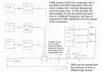
I've sketched a quick principle diagram for let you know what i mean, but the circuits that i had used for my application don't work with this one (they was sending two different BCD codes down on 10 and 12,7 MHz, and sending back a video signal on a modulated 30/35MHz signal) ..... need to redesign all the circuits, for this application ..... anyway, it was working with 3 different signals overimposed on a DC power supply line, that is, basically, he same thing that you need here (controlling 3 different loads with a single signal), so i don't see why it have not to work .....

attachment.php


The only "problematic" part can be the sintony circuits for separate the 3 signals at the arrival, cause the carriers are not so high frequencies, but it can be done using the same sintony circuits from AM radio deceivers .....
 

Attachments

  • overimposed modulation principle.jpg
    overimposed modulation principle.jpg
    147 KB · Views: 3,183


Back
Top