Welcome to Laser Pointer Forums - discuss green laser pointers, blue laser pointers, and all types of lasers

Buy Site Supporter Role (remove some ads) | LPF Donations

Links below open in new window

FrozenGate by Avery

Laser for hobby CNC-use?

My personal favorite is actually jst connectors on wires.
I get em from hongkong:
JST Cables (10-Pair) - Free Shipping - DealExtreme

I use the header-symbol regardless though, and just solder the wires to the pads. Makes for nice boxes. I equip all my Aixis modules with a male jst so I can swap em around. They do fit my psu plug too so better from crossing the wires hehe.


As for the opto:
I like optos. Also, this opto is cheaper than a cheap fet-driver and it has push/pull which allows much better switching. Also the isolation it provides helps to avoid getting capacitive pulses from the switching through the gate of the fet and into the microcontroller.

I do a lot of stuff with microcontrollers. Not because it is easier/better and definately not cheaper, but I like em and have fun using em. It also allows more advanced behaviour than you can get in analog setups. Especially if you try and keep em simple.

In this case it finally gave me a reason to play with one of the new ATtiny10's I received a while ago.

The Tiny10 can be programmed with a usb-serial dongle without level converter and avr-dude. Or a proper supported programmer.
In case of the hack programmer, it just needs the usb ftdi-like thing and a resistor.

When I have this working to my liking I will post full dataset on it, including design, source-code and binaries. Should allow one to be built with minimal fuss. It does require some surface-mounted soldering but nothing advanced.

Do you think hole-mounted headers may be better?
So they stick up on other side of board together with the trimpot?
I'm starting to wonder. If I order boards, I may as well go 2-sided too. For now I can proto it 1-sided... (I hate riveting vias.)
 
Fiddled with it some more.
I recalculated and it is safe to use the 12v bootstrap the way I do. FET gate will never see more than the pump voltage of 12v. That means it's ok to supply it with 15-16v too. So 6-16v supply :)

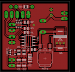
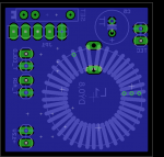
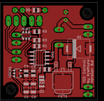
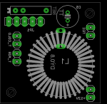
I also adjusted the layout a bit using through-hole headers to get all connections and adjustments on other side. Swapping out the cap made sure the circuit won't be as bulky on the surface-mounted component-side. Switching to a toroid inductor to handle the current and getting it to the other side as well made it all much nicer.

Attached are images of the new setup. Looks neater and best of all, gives copper flood for cooling to the FET. I can nail the diode to the groundplane if it gets hot too.
 

Attachments

  • tec-reg_v0.5_sch.png
    tec-reg_v0.5_sch.png
    8.6 KB · Views: 976
  • tec-reg_v0.5_pcb_a.png
    tec-reg_v0.5_pcb_a.png
    18 KB · Views: 662
  • tec-reg_v0.5_pcb_b.png
    tec-reg_v0.5_pcb_b.png
    23.1 KB · Views: 574
I should be etching it already but I can't stop fiddling with it.
I decided to make it one-sided for now and by moving some stuff around I got a much better high-current path.
The noise created on the supply shouldn't be a problem for the regulator but we'll see.

Atleast now it's much better on the Power/FET/Diode/Inductor/Ground-loop.

I think I'll etch this one.
 

Attachments

  • tec-reg_v0.6_sch.png
    tec-reg_v0.6_sch.png
    12 KB · Views: 387
  • tec-reg_v0.6_pcb_a.png
    tec-reg_v0.6_pcb_a.png
    18.7 KB · Views: 1,858
  • tec-reg_v0.6_pcb_b.png
    tec-reg_v0.6_pcb_b.png
    18.6 KB · Views: 1,261
I use UV transfer with philips daylight-bulbs (perfectly safe but 15 min exposures needed) and I etch with sodium persulfate which is safe and doesn't create nasty fumes.
It's also clear allowing you to see what's going on. (Turns crystal-blue when used.)

I use a side-mounted magnetic stirrer on my tank instead of bubbles as this doesn't spray the salt everywhere but works just as well although a tad less even.
I etch in my bathroom...
 
I found using the "sponge" -> Sponge + Ferric Chloride Method -- Etch PCBs in One Minute! method works suprisingly well.

Basicly you place just enough ethcnat in the container with the board and use a sponge or I prefer a sponge brush, to soak up most of the etchant then lightly go over the board with the sponge and in a just a few minutes the board is nicely etched, and you wasted VERY LITTLE etchant.
 
Can't even buy ferric chloride here. It's considered a toxic and harmfull substance.
Btw, I hope you dispose of those sponges safely as some experienced them combusting or causing other stuff in garbage to do so.
 
I see everyone has sort of drifted from the main thread topic so if I may do the same.
If you are worried about eye damage etc can't you completely enclose your CNC and put a web cam on the Z axis to keep an eye on things from a safe place? I think most webcam already have an IR filter built in to make it easier.

I like the webcam idea simply for looking at it and taking nice videos.

Also, I've been getting some comments saying I could use IR even though I distrust invisible beams. The IR has apparantly better absorption, especially for clear materials and white ones.
I'd like to cut thin acetate for solder stencils and white depron in 3mm sheets.
It cuts 3mm black depron like butter for the moment, but I'd really like being ablwe to cut white too.

Things would definately be a lot easier if I could cut solder stencils out of acetate. I see 808nm is quite cheap, and teh C mount diodes go as high as 10w in a single 200nm chip!
I'd have to order a new set of goggles from dragonlasers though. They have some OD3+ for IR.
 
The problem with me is I don't trust myself. If I had a cutting laser set up with no safety devices, it would only be a matter of time before I switched it on forgetting to put the glasses on or maybe the wrong glasses etc etc. If at all possible I would always recommend eliminating the hazard. I.e. boxing it in completely so no light can escape that way it doesn't matter what frequency laser you use. Incidentally if you take the IR filter off a web cam (which is normally fairly easy to do) you can then observe an otherwise invisible beam as it'll show up white. I would also put switches on my enclosure to prevent the PSU's powering up without all the guards being in place of course you’d need ventilation as well but then you’ll probably need that anyway as vaporised plastic aint nice stuff to breath.. Still that's just me... and I still have accidents :(
 
The problem with me is I don't trust myself. If I had a cutting laser set up with no safety devices, it would only be a matter of time before I switched it on forgetting to put the glasses on or maybe the wrong glasses etc etc. If at all possible I would always recommend eliminating the hazard. I.e. boxing it in completely so no light can escape that way it doesn't matter what frequency laser you use. Incidentally if you take the IR filter off a web cam (which is normally fairly easy to do) you can then observe an otherwise invisible beam as it'll show up white. I would also put switches on my enclosure to prevent the PSU's powering up without all the guards being in place of course you’d need ventilation as well but then you’ll probably need that anyway as vaporised plastic aint nice stuff to breath.. Still that's just me... and I still have accidents :(

Yeh, I already have a ir webcam.
I have tested a few green LD's to see the ammount of IR by using green blocker, and I found I needed filter on my green 50mW (so I added the IR filter from the $3 webcam to it).

Also, the only part that I want the lid to shut off is the laser. I use it for cnc milling too so I want it to run for the milling.
So far I haven't had enough power to create much fumes though, but I have a suction-fan for such fumes already and will be usi8ng it if I can just get the power up.

I see I can get 2w or even 3-5w c-mount LD's with FAC which makes it a nice 3/8deg divergence. By placing the first element of the colminator at the right distance I can then get quite a good and wide beam that I then feed to the focusing lens. Using 40mm lense should give me quite a good and small focal point. I'll order some glasses first and then have a look at the cdrom lasers. Then I can see how the mw compares on my acetate.

I can't any comparisons of this anywhere so if someone has a medium or atleast burning power ir laser I'd be happy if they tested it on some acetate (overhead transparrancies for copiers) to see what it does.
With my red at 250mW I have to blacken the acetate with a sharpie, and even then I don't get a clean cut in one pass.
 
Sounds like an interesting project you've got there. I'm in the process of building a CNC router (a long standing project I’m afraid) so something like this along with a 3D print head will be an obvious addition if I ever get it done :)
Now to ask a nooby type question, if you use a normal LED to set up the focussing arrangement will the focus be different with a different wave length light as in a LD? I imagine it would so if this is the case is it easily calculable what the difference would be? The reason I'm asking is would it be possible to build an auto focus on your Z axis but using standard LED's. My views are as things in a typical DIYer set up can often move a little then to have an auto focusing arrangement may keep it at its optimal focus and distance....just a thought.

Short ansver: Yes.
Long ansver: The colmination and focusing assembly is dependant on the size of the emissive element in the laser as that together with the divergence dictates the position of the element vs lense and the mean width I get. If I had a light source with the same propertys I still could not do it as you are right that the wavelength also has a lot to do with the total result.

I've run sequences of NC code to check my focus.
Basically the code generates a ruler but moves the z axis linearly as it draws. One can then simply read the correct focusing distance from the plot as that is the sharp area. I've attached a picture of it. This focusing can be done without looking at it too.

For a DIY'er I find that focusing on a far distance actually gives a better cut even though it does not create as sharp a focal point. Reason is the dof is higher. For 3mm depron I need atleast 60mm to focus point or I get less than 3mm dof resulting in a coarser cut. I can do 0.1mm wide cuts straight through 3mm black/gray depron btw!
 

Attachments

  • laser_focustest_3_s800.jpg
    laser_focustest_3_s800.jpg
    339.6 KB · Views: 855
Last edited:
Ah yes that makes sense. Another way would be to have a very small thermo couple junction and aim it at that. Something like a square of ally with an insulated target of whatever spot size you want in the middle connected to a T/C. Aim the laser and let the software tune it for max temperature. If the laser spot is too big you’ll lose energy/heat and if it’s too small then the temp will be the same. So the focusing will be just right as the temp curve flattens out. A routine could then be put in to the CNC to check calibration of the LD every once in a while.
 
Ah yes that makes sense. Another way would be to have a very small thermo couple junction and aim it at that. Something like a square of ally with an insulated target of whatever spot size you want in the middle connected to a T/C. Aim the laser and let the software tune it for max temperature. If the laser spot is too big you’ll lose energy/heat and if it’s too small then the temp will be the same. So the focusing will be just right as the temp curve flattens out. A routine could then be put in to the CNC to check calibration of the LD every once in a while.

You really have to build a horrible cnc to have such poor control of the z elevation. Mine is built of wood/metal combination and still has better than 0.05mm accuracy.
Since the spot I focus to is smaller than 0.1mm diameter using a target is simply not fesible. For measuring power output however I use as much as possible of the target surface of my 15x15mm TEC as sensor.


Back
Top