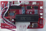
Yep I have one of those - I just spent the last minute or two removing a solder blob from those pads.
Sweet, can you tell me what pins they lead to on the MCU?
Both of the ones I have are in projectors at the moment.
Just for reference, there are a few variants of this particular board I have seen. One of them has an additional row of unpopulated resistors between the pads I pointed out, and the MCU, one is missing these component positions entirely.
The MCU they use can vary also. Some use the STC , and some use the Winbond MCU. However these are identical 8051 based MCU's, just different manufacturer.
They come in various solder mask colors as well. One of mine is red like the pic, and one is yellow, however they are electrically identical.
Im just pointing this out as if we get this to work, it will likely work with 98% of the show cards out there, even the iTrust card.
One good thing about the PatternISP app, is it has the ability to READ the data from the MCU back to the PC. That way, we just test connection with reads, so we dont potentially corrupt the MCU. When we figure out a port, and get a good read, then we can write.
One thing we will need to make certain of, that we have no information on, is just how many patterns we can store on the MCU. Some of the DATA space may be used by the program. If we write to that space by cramming to many patterns in, it may render the MCU essentially dead. The app may have some checks for this, but there is no way of knowing for sure without some documentation.


