Welcome to Laser Pointer Forums - discuss green laser pointers, blue laser pointers, and all types of lasers

LPF Donation via Stripe | LPF Donation - Other Methods

Links below open in new window

ArcticMyst Security by Avery

How do you test your laser drivers?

reloader45

Active member
Joined
Mar 17, 2019
Messages
172
Points
28
Hello,

today I had bad luck again with a 500 mA buck/boost driver. It was not from DTR!
I connected the new driver to my dummy load of 6 diodes and a 0,1 Ohm resistor. Nothing happens, no curent draw from my laboratory power device.
After checking the wiring, the same result. Is it possible to kill the driver while soldering?

After building a working test device for laser diodes with a LM 317, I will build a test device for laser diodes drivers without soldering.
The quality laser drivers are simply to expensive to play the private laser diode driver tester.


best regards

Edgar


Joined
Sep 20, 2013
Messages
17,413
Points
113
You can lose one if the connection to the dummy load is intermittent. Anytime you lose your load, even for a short period of time, the driver tries to force current to flow through an open circuit and that is when you can lose a driver. The LM317 based drivers are linear and not conditioned on having a load, so much more forgiving.

I can't see you losing one while soldering unless you apply so much heat that solder flows on other parts on the driver. I never lose drivers when setting them up, so I know it is not a common problem. If you buy them from DTR he will set them up for you, but you will have to ask him to do that. Otherwise, there are switching drivers that aren't adjustable, so if you are okay without testing them prior to using, you should be okay most of the time.
 

reloader45

Active member
Joined
Mar 17, 2019
Messages
172
Points
28
Dear Paul,

the positive cable of the load was soldered, the negative was screwed, so both connections well done. After that, I connected the Driver with the power supply.
Nothing happened! After that, I checked the dummy load again, everything was ok.
Then I took my last 5500 mA Driver and set the current to 1800 mA with my dummy load, no problems at all.
Meanwhile I think, that not all seller test their drivers before shipping.
I like to buy from DTR! The only problem are the high shipping cost to Germany. I do not like to pay 12 $ shipping for a tinny 25 $ Driver.
I will build a laser Diode Driver test device with spring loaded contacts to avoid soldering or short curcuits.


best regards

Edgar
 

reloader45

Active member
Joined
Mar 17, 2019
Messages
172
Points
28
Hello,

my test device for laserdiode drivers is under construction. The construction is more difficult, then I thought before starting.
The contact holes of my 1500 mA driver have a distance between 8 mm and 3 mm. The problem is the 3 mm distance.
I am still thinking about how I can contact the driver rock solid with the wiring cables without soldering. Every idea is welcome.
Reading the specifications of the 500 mA driver again, I noticed, that the upper supply voltage is 9V.
Meanwhile my laboratory power supply is under suspect. I am not sure, if I got the 8,4 V that the voltmeter shows.
So I will switch to Lithium ion batteries to test the drivers in future, just to avoid voltage spikes.
I am not really sure, but I think, that my laboratory power supply is a silent killer, responsible for the early death of some laser diodes and drivers.

best regards

Edgar
 
Joined
Sep 20, 2013
Messages
17,413
Points
113
As to your power supply, you might try setting the voltage to 0 and shorting the cables once it is powered up before connecting it to a laser diode. That is what I do. I use a transistor socket with leads soldered on it to hold the diode and only after shorting the leads on the PS do I connect it together. Then I can slightly increase the current limit before I increase the forward voltage to the diode.

On a test jig, the ones I have seen that work well have a pointed contact with a metal base that is used to make connection with the driver input and output holes. That way these pointed contacts seem to make a better connection with the drivers. These are movable to be useful with a number of different drivers. So, you have four pointed contacts that you place your driver into. I don't have this, but from the people who do, they seem to work very well to setup a large number of drivers very quickly.
 

reloader45

Active member
Joined
Mar 17, 2019
Messages
172
Points
28
Hello Paul,

thank you for your information.
I finished the driver test device. It works well, but I do not like the design. It is to complicated and can`t be changed easy for drivers with different dimensions. For the power supply, I used two Li accus, so the driver is still alive.
I understand your desciption of the test jig, but it would be helpfull to see some photos.

I do not drive any laser diodes directly with the laboratory power supply anymore. For the purpose of testing, I use my LM 317 constant current device.


best regards

Edgar
 
Joined
Sep 20, 2013
Messages
17,413
Points
113
Sorry, I don't have a photo to show you. I know that Jordan, DTR, uses one of these. You might get help from him on the test jig.
 

reloader45

Active member
Joined
Mar 17, 2019
Messages
172
Points
28
Hello,

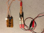
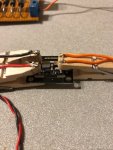
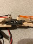
as I told you, I did not like the design of my first laser driver test jig. Today, I built a very simple one with wooden clamps. It looks cheap, but ist work well.

best regards

EdgarIMG_0278.jpgIMG_0279.jpgIMG_0280.jpg
 
Joined
Sep 20, 2013
Messages
17,413
Points
113
Looks pretty good, but you still have a problem with not being able to move the contacts for other drivers.
 
Joined
Jul 10, 2015
Messages
9,898
Points
113
Hello,

as I told you, I did not like the design of my first laser driver test jig. Today, I built a very simple one with wooden clamps. It looks cheap, but ist work well.

best regards

EdgarView attachment 66856View attachment 66857View attachment 66858

Very nice and the spring tension keeps contact. (y)


Looks pretty good, but you still have a problem with not being able to move the contacts for other drivers.

So he makes a test jig for each style of driver, I think it's a job well done.
 
Joined
Sep 20, 2013
Messages
17,413
Points
113
I said it looked good. Just mentioned something we had posted on it previously. Was totally unnecessary to point to the obvious. But, whatcha gonna do?
 
Joined
Jul 10, 2015
Messages
9,898
Points
113
Looks pretty good, but you still have a problem with not being able to move the contacts for other drivers.

If it was obvious then why did you use the word " problem " ?

You noted a problem and I supplied an answer, if my answer was so obvious in retrospect that you felt the need to malign me then your issue is with yourself.
 

reloader45

Active member
Joined
Mar 17, 2019
Messages
172
Points
28
Hello,

please don´t quarrel!
As I said, it is just a quick and dirty construction. Paul is right, I need another contact, if the holes of the driver output have a different distance.
The power input will work for different distances.
I always got good advice from Paul and I think, he is really willing to help.
I also thought about single contacts for the driver output. But with a distance of only 3 mm, the construction has to be stable to avoid deadly short circuits.
So I drilled the holes with the help of my milling machine and the digital readout.

I am thinking about a more simple universal jig with spring-hard bronze contacts, mounted on a acrylic glas plate.
But first, I have to order the bronze.

best regards

Edgar


Top