Welcome to Laser Pointer Forums - discuss green laser pointers, blue laser pointers, and all types of lasers

Buy Site Supporter Role (remove some ads) | LPF Donations

Links below open in new window

FrozenGate by Avery

How boost converters work

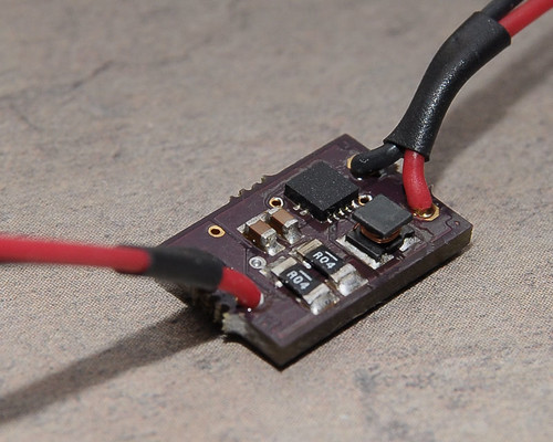
To make a constant current source you put a small resistor in series with the load and measure the voltage across it. More current means more voltage across the resistor, so you use that to determine the current flow and thus cut-out point. That thing that gets hot in the flexdrive, that's a current shunt resistor.

Sorry for the double post, I thought I clicked the edit button...
 
Last edited:


I think i'd sooner shoot myself in the foot than try to derive the equations for a switching power supply. Datasheets will give you approximations for ripple calculations but these are rough non theoretical equations based on product results. Also, its not constant current or voltage, there will be a ripple based upon your capacitance. Also depends on the ESR of your caps and a few other complicated thingeys. Even if you make a PCB you won't get the datasheet results unless your pcb coper plates are of proper sizes and your trace widths are the proper size and length!

So.. even the capacitance and stray inductance of the traces even affects the shape of the ripple? That's insane. How horribly frustrating that must be to work with!

To make a constant current source you put a small resistor in series with the load and measure the voltage across it. More current means more voltage across the resistor, so you use that to determine the current flow and thus cut-out point. That thing that gets hot in the flexdrive, that's a current shunt resistor.

Sorry for the double post, I thought I clicked the edit button...

Oh... so trivial ohm's law right there.

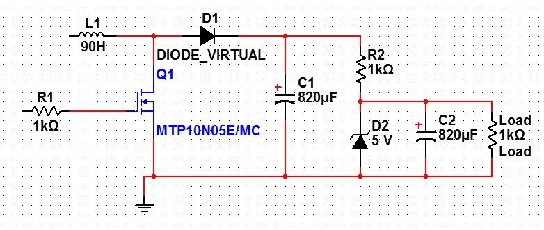
So why couldn't one simply put a zener across the load, and use the series resistor to drop the ripple that exists across it?

I've been told that switching supplies are "noisier" than linear supplies, so really you should be able to take care of that issue if you simply drop that noise across something that doesn't affect the bias of the zener.
 
Ripple isn't exactly all that important when powering just a laser diode. Usually it becomes a problem when powering microelectronics, in that case one could just use a larger capacitor or a filter inductor to reduce ripple.

Putting a zener in // with the load is a poor idea because it would be very wasteful and the zener would likely blow up too. Zeners are typically used for creating a reference voltage for linear regulators.
 
Ok, so doing this would blow up the zener?

Switchingsupply.jpg
 
Yes. Essentially you just mixed a linear and switchmode regulator together.

Also, 90H is a bit much (unless you are trying to boost 3V into 30,000)
 
Niiice a 90H inductor? That would be one interesting boost converter haha. Surprisingly it would'nt be toooo exspensive. Heres a 150H inductor for 18 bucks Digi-Key - 156C-ND (Manufacturer - 156C). Except you would need one mighty cap if you wanted to make good use of that inductance.

Another tricky thing about switching supplies is that the output voltage will drop if you draw more current then what the LC network or the chip can supply. So while adding that resistor in series may work on some switching supplies(the ones that have the right type of feedback) your still going to run into issues. Also, if its strictly a boost chip, the chip will shutoff if you attempt to output a voltage lower than the input.

Anyone know if the flex drive is Boost or Buck/Boost or Sepic?
 
Last edited:
Yeah... please ignore the arbitrary component values. I don't know the switching supply working calculations, though they would be nice to know! I was just trying to show the setup I was thinking of.. and if I am to interpret grenadier's answer right, the zener would blow up. :(

I've got my inductance, solendoid, XL, XC, magnetism, and capacitance equations handy but where's a good a place to start with piecing a circuit together?

What type of IC's should I search for?
 
Check websites like National Semiconductor | High-performance Analog and Fairchild Semiconductor | Power Management & Mobile IP Solutions for switch mode power supply stuff.

I'm a fan of national's simple switcher stuff myself: SIMPLE SWITCHER Power Modules, Voltage Regulators, & Controllers | National Semiconductor ? Switchers Made Simple, Switching Regulators/Converters, Simple Switcher Modules, Controllers, Switched-Capacitor Regulators, Buck, Boost, & Buck-Boost Regulat

But, why not just go with a 555 timer? It has a reset pin, just put your interrupter there. Drive the mosfet with the 555 set to 30khz or something around there, and pick an inductor. How much voltage do you want? 100uH would be good for around 170 to 400V, while smaller values are ideal for smaller voltages. IIRC the inductor in the microflexdrive is 3.3uH, but I'd go a bit bigger than that myself.
 
Anyone know if the flex drive is Boost or Buck/Boost or Sepic?

IIRC its based on a TI TPS63xxx series Buck/Boost IC ... the one in the BGA package.

Ive successfully built a driver based on a TPS63000 using a INA193 instrumentation amp on the FB to measure the drop across the set resistor. The problem is 1) its not settable except to change out the resistor 2) the TPS and INA chips are f*ing expensive in small quantities.

 
Last edited:
IIRC its based on a TI TPS63xxx series Buck/Boost IC ... the one in the BGA package.

Ive successfully built a driver based on a TPS63000 using a INA193 instrumentation amp on the FB to measure the drop across the set resistor. The problem is 1) its not settable except to change out the resistor 2) the TPS and INA chips are f*ing expensive in small quantities.


looks cool, op amp on the other side? Its nice that the chip is a buck boost that automatically switches between modes and doesn't require extra circuit topology for the buck/boost switch. Good choice, but yea, expensive. It also won't handle 2 batteries... be nice if it had a wider input voltage range.
 
Being that the flexdrives' components are bought in bulk quantities, how much do you figure those cost to build? :thinking:
 
Being that the flexdrives' components are bought in bulk quantities, how much do you figure those cost to build? :thinking:

A Flexdrive probably costs on order of $5 for parts and SMT soldering in quantity.

We should not, however, believe that a product's manufacturing cost should be the governing factor in its price. There are development costs, part costs, and assembly costs among other things. None of those guarantee a return on investment. Great risks can lead to great rewards to those who put forth the effort and are willing to suffer setbacks for greater gain.

Oh, and next time when you post, look at the date of the last post and see if you really should be resurrecting a post that old.
 
Last edited:
Thanks for the tip, I didn't realize posts had expiration dates... I suppose in this forum, I should have started a new thread "how much does it cost to build a flexdrive" - sorry I forgot where I was for a minute - lol

(might wanna unsubscribe to some of these older threads btw)
 
Last edited:
I'm not actually subscribed to this, or any, thread. However, threads float to the top if there is a new reply. This can be annoying because the content is usually not that relevant anymore, which is partially why there are no new replies. If you want to reopen a subject with respect to another thread the protocol is usually to start a new thread and reference the old one.


Back
Top