Welcome to Laser Pointer Forums - discuss green laser pointers, blue laser pointers, and all types of lasers

LPF Donation via Stripe | LPF Donation - Other Methods

Links below open in new window

ArcticMyst Security by Avery

Help with LM317 laser driver

Joined
Mar 14, 2014
Messages
2
Points
0
Hi,
I'm new here, so please forgive my ignorence...

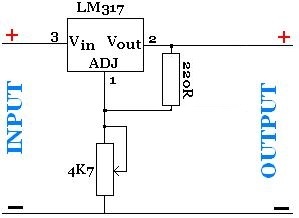
Here is a driver I made :
65ch.jpg


And here is the caracteristics of the diode :
445nm%20-%203x%20PIV%20Plot.PNG


Now, here is the problem :
It perfectly works, no overheating,...
On the laser diode, it shows : 550mA and 4,5V and that's exactly what I want.
But, theoretically, shouldn't I get the 15V of the power supply ? So isn't it dangerous for the laser diode ?

Thank you for any answer, I'm lost :thinking:


Things

0
Joined
May 1, 2007
Messages
7,517
Points
0
No, because you are current limiting, the forward drop of the diode is the highest voltage you'll see.
 
Joined
Mar 14, 2014
Messages
2
Points
0
I thought I had to be as follow to limit correctly :
adjustable-power-supply-with-lm317-voltage-regulator.jpg


But If I am, that's good and thank you ! :)
 
Joined
Jan 14, 2009
Messages
1,452
Points
83
In your first post the picture shows the regulator acting as a current regulator , it will deliver a fixed current and then drop a voltage over its self , the voltage drop over the regulator + the voltage drop over the diode will equal the 15V you started with .

So with 4.5V over the diode , there is 10.5 Volts over the regulator and thus the regulator is dissipating 10.5*0.550 = 5.7 Watts in heat .

The picture in the second post above this one , that circuit is the regulator as a voltage source , thus is will give a fixed output voltage and the current is able to vary with the load .
 
Last edited:
Joined
Jul 13, 2010
Messages
98
Points
8
Here is a link to a neat calculator for LM317/338/350 circuits. There is one for voltage, and one for current (depending on the way you wire the circuit). I used a pot for the resistor, so I can adjust mine.

LM317 / LM338 / LM350 Voltage Regulator Calculator and Circuits

What's extra cool about this is that you can input any value for the resistors so you can come up with a fixed resistor that is correct for the range of the pot you use. If you use a pot to make it variable like I did, make sure that you include an extra one ohm resistor in series with the pot so that you can't make that value zero, it will always be the pot's value plus one ohm. Zero ohms will overload the diode for sure.
 
Last edited:

IsaacT

0
Joined
Aug 25, 2010
Messages
5,947
Points
83
Here is a link to a neat calculator for LM317/338/350 circuits. There is one for voltage, and one for current (depending on the way you wire the circuit). I used a pot for the resistor, so I can adjust mine.

LM317 / LM338 / LM350 Voltage Regulator Calculator and Circuits

What's extra cool about this is that you can input any value for the resistors so you can come up with a fixed resistor that is correct for the range of the pot you use. If you use a pot to make it variable like I did, make sure that you include an extra one ohm resistor in series with the pot so that you can't make that value zero, it will always be the pot's value plus one ohm. Zero ohms will overload the diode for sure.

Rad site! Many times when I was making my first lasers I would be baffled by ohms law for 30 minutes with a pen and paper trying to figure out what did what and how it all worked. That calculator should prove very helpful to people! +rep
 
D

Deleted member 16589

Guest
Here is a link to a neat calculator for LM317/338/350 circuits. There is one for voltage, and one for current (depending on the way you wire the circuit). I used a pot for the resistor, so I can adjust mine.

LM317 / LM338 / LM350 Voltage Regulator Calculator and Circuits

What's extra cool about this is that you can input any value for the resistors so you can come up with a fixed resistor that is correct for the range of the pot you use. If you use a pot to make it variable like I did, make sure that you include an extra one ohm resistor in series with the pot so that you can't make that value zero, it will always be the pot's value plus one ohm. Zero ohms will overload the diode for sure.

cool site I use to use that site
but if you don't mind a download I use this program it lets you type desired current and it tells your resistor.

Regulator Designer Volatage Current Shunt Adjustable
 
Last edited by a moderator:
Joined
Jul 13, 2010
Messages
98
Points
8
I built a driver that combines both, using 2 LM350's, the first configured as a variable voltage regulator to feed the one configured as a current regulator, which is also set up as variable. It's very handy.
 

IsaacT

0
Joined
Aug 25, 2010
Messages
5,947
Points
83
I built a driver that combines both, using 2 LM350's, the first configured as a variable voltage regulator to feed the one configured as a current regulator, which is also set up as variable. It's very handy.

Is this just to reduce the amount of heat given off by the current limiting circuit? If not why have both? I thought that you could either limit current or limit voltage, not both?
 
Joined
Jul 13, 2010
Messages
98
Points
8
Is this just to reduce the amount of heat given off by the current limiting circuit? If not why have both? I thought that you could either limit current or limit voltage, not both?
That's why I used 2 LM350's. I have a voltage regulator feeding the current regulator, so I can adjust both the voltage and the current for different diodes. Reds like low voltage, while blues like more, and the new green diodes are outrageous, they like a lot more voltage. By feeding the thing with a 9v to 12v power supply, I can get any output combination I need out of it. Adjusting the current output doesn't change the voltage at all, and vice-versa.

An example of how I use my test driver: lets say I have a new diode, and a new driver to go with. First, I power up the new driver, and measure the output voltage. Then I get my test driver, and adjust the voltage until it's the same as my new driver. Then, with the current on my test driver set down to null, I connect the new diode, and gradually increase the current until my diode thresholds, and gets nice and bright. Now I connect my test driver to my dummy load, and measure the output current, as set where the diode likes it. Then, I connect the new driver to the dummy load, and adjust that so that the output matches what my test driver has. THEN, and only then, it's time to solder the new diode to the new driver, now that it is properly adjusted.
 
Last edited:
Joined
Jan 14, 2009
Messages
1,452
Points
83
In Current regulation mode if the circuit is feed from a given voltage above the V drop of the regulator , resistor and laser diode , then any laser diode can be run simply by changing the resistor to set the driver current to suit that diode .

By having two regulators all that's happening is the heat dissipated by normally one regulator is now being dissipated over two regulators , Its the same as having a variable voltage bench supply feeding a current regulator

Sure for a lower forward voltage diode from a given voltage , the regulators will dissipate more heat then from a high forward voltage diode from the same supply , But from a fixed voltage such as 12V its still a linear regulator so its just heat in both regulators and light/heat from the diode by the end of it ,
 
Last edited:
Joined
Sep 12, 2007
Messages
9,399
Points
113
I built a driver that combines both, using 2 LM350's, the first configured as a variable voltage regulator to feed the one configured as a current regulator

You've made a mistake. If you have the voltage regulator first, the current regulator will drop more voltage and you will loose your voltage regulation.

You want the current regulator first.

I thought that you could either limit current or limit voltage, not both?

If you meant regulate instead of limit, you are correct. Assuming mister GVLLD makes the correction I outlined above, it will be in EITHER current regulation OR voltage regulation - whichever of the two setpoints is lower.
 
Last edited:


Top