

grainde
0
- Joined
- Jan 29, 2012
- Messages
- 3,163
- Points
- 113
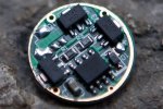
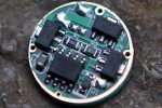
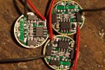
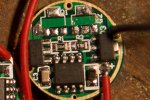
I've just received my AMC 7135 1050 mA driver from Kaidomain and I want to modify it to 750 mA, in preparation for the new laseerer 3.8 mm diodes!
Here is the driver I bought, for anyone who might be interested.") : http://www.kaidomain.com/product/details.S009743
: http://www.kaidomain.com/product/details.S009743
I know I have to remove one 7135 chip from the board, but as there are 3 to choose from, I'm not sure which one. I guess they're all in parallel and it doesnt really matter, but I thought I'd check just to be sure! The one in position Q2 would be easiest, as it is the most accessible...Any thoughts??
Any help / comments would be much appreciated! :thanks:
Here is the driver I bought, for anyone who might be interested.
: http://www.kaidomain.com/product/details.S009743 I know I have to remove one 7135 chip from the board, but as there are 3 to choose from, I'm not sure which one. I guess they're all in parallel and it doesnt really matter, but I thought I'd check just to be sure! The one in position Q2 would be easiest, as it is the most accessible...Any thoughts??
Any help / comments would be much appreciated! :thanks:
Attachments
Last edited:


")
 Foulmist the red setting ie pin 3 has 3 diodes. Sorry forgot to mention it.