Welcome to Laser Pointer Forums - discuss green laser pointers, blue laser pointers, and all types of lasers

Buy Site Supporter Role (remove some ads) | LPF Donations

Links below open in new window

FrozenGate by Avery

Help wiring a flyback transformer.

Found this post and the most common advice is to put a 10 W 10 Ohm resistor between +5V and GND.

I've found a tutorial saying PSUs made after 2003 should instead be hooked with a 22 Ohm resistor on the +12V line instead.

I'm also starting to suspect the wires may be too thin. I used 20AWG wire to hook it up.. Do I need to replace it?


Edit: Le Quack posted before I finished editing, ignore this :P
 
Last edited:


I keep on hearing that too, but what does that mean? I've only had to pull 6A @ 12V, but if it can supply that without actually being "on" then why bother loading the other rails?

The reason being why most switching power supplies require a load is due to regulation...

When a power supply has nothing to do, it'll send a few small pulses out to fill the filter caps, then sit there. If too light of a load is used then the "pulses" are too far spaced out, and the power supply is out of regulation. Thus you need to pull more current so that the power supply can regulate itself.

Regarding the wire Atomic, you could probably use 18 gauge wire and be better off. 20 gauge might be cutting it a little too close.
 
I decided to risk my multimeter and take some measurements!
With the flyback on voltage drops from 12V to about 10.5V. Drop seems to increase only a little bit when I turn the potentiometer.
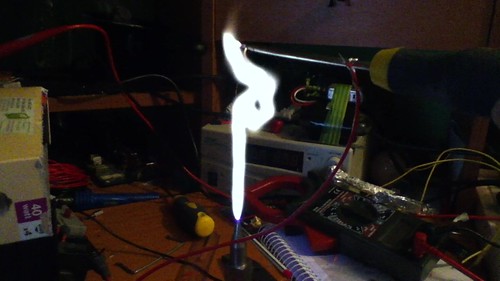
Current seems to depend mostly on arc length - small arcs (purple and continuous) draw about 0.5-1A.
If I increase the distance to get longer arcs (blue-white, "popping" all the time) current increases a lot and starts to vary wildly - the maximum I got was slightly over 7A, with an average of about 2-3A.
Turning the potentiometer to increase power while keeping the wires close still draws less than 1A. Even pulling little current the PSU shuts down on it's own.

I must be doing something very wrong...
Do you think the load resistor will help?
 
Yes, this is a clear case of the PSU dropping out of regulation. The 10.5V is a dead ringer for that, that is the definition of dropping out of regulation. I'm surprised you can pull that much current before shutdown... rails should not drop more than 0.5V when regulated. Do the resistor install, and don't skip out on the wattage rating of the resistor, more is always, always better.
 
Got the resistor - it's a tube wirewound, couldn't find the sandbox - now it doesn't shut down anymore :)

The resistor gets warm pretty quickly and the driver mosfet gets much warmer as well. I'm using 15 windings on the primary ATM.

The strange thing is that with a continuous arc (or no arc at all) the voltage stays very close to the 12V but when I get the HV wires far enough to start popping the voltage goes up to about 14V. Do I need to worry about that?
 
Sorry about the triple post but I have some updates :P

Managed to get an arc of about 3.5cm by slowly decreasing the amount of windings. Got to about 7 turns before the flyback suddenly started arcing everywhere.

I'll revert to 14 windings, the mosfet stays warms and there's no unwanted arcing.

I think the arcing affected the insulation of the primary wire. Can I use multi-stranded non-copper wire with plastic cover on the primary? I've never seen any coils with that but if it's not a problem I think the insulation will be considerably better.

I'm also curious if the high pitch noise relates to the frequency of the circuit.
 
Yes the HF whine is from the magnetic oscillations making vibrational oscillations due to megnetomotive force.

What do you mean by "flyback suddenly started arcing everywhere". Be specific where arcing occured (from where to where).

The core should be insulated from the primary wire by several layers of electrical tape. The core is a conductor and you can short out the primary and blow your driver if you don't insulate the core. Do not use non-copper wire, but stranded is fine. You can use standard insulated speaker wire with great success, just make sure it is at least 14ga. (as in thicker, which is a smaller number).

The mosfets and resistor are going to get warm during proper operation. These devices generate a LOT of heat, so proper heatsinking is important. Don't just use wimpy radioshack TO-220 heatsinks, you need REAL heatsinking. For the resistor.. as long as it isn't so hot that it will melt plastic brought against it, it'l be fine. I've actually run wirewound resistors so hot they glow incandescently.... but that is NOT proper, haha.

IMO do not tune your primary so that the mosfets stay cold and you get wimpy output. Tune for maximum output and then increase the heatsinking as necessary to ensure safe temperatures at appreciable run times. Upgrade to insulated primary wire and make sure you insulate your core with electrical tape first. Then go back to retuning.
 
Well it's hard to say, there was just too much arcing and I turned it off to avoid damage. At the very least it involved various bottom pins (even though I cut them off and sealed with hot glue) and the core itself. Someone said they saw an arc hitting the primary but I'm not sure.

Didn't know I had to insulate the core, will do it right away!

I don't think 14 wire will fit at all, 20 is already hard to insert between the core and the plastic.

heatsink.jpg


As for heatsinks I think the MOSFET one is fine, it used to hold 3 transitors :)
I could try to add a computer fan to it, I have some spares around here.

LOL @ incandescent resistor - must try that someday XD
I just attached the resistor to the PSU case with some thermal paste but the contact is very poor because the resistor is round. Do you know a better way to heatsink a round resistor?

That's great advice, I'll try it. But I have to find a way to stop the unwanted arcing without sinking it in oil. Oil is waaay too messy!

I do have another question - can I solder some wire to the HV+ to extend it? I'd like to mount the flyback on the top of that green box but the wire is just too short.
 
Of course you can solder on wire to the HV+, just make sure you insulate the joint well, and TEST THE WIRE'S INSULATION FIRST.

To test the wire insulation, take the wire in question and take a bare copper wire of the same length or slightly shorter, and twist them together. Make sure the ends of the two wires are several inches apart on BOTH SIDES. Temporarily connect the HV extension wire to the +HV and the bare wire to the HV return/ground. Fire it up and if you see corona or hear hissing the insulation will hold for short periods of time, but try not to let the new HV lead contact anything sensitive or metal, and certainly don't touch it while on, but it will be OK to use with caution. If it arcs over immediately and sets the insulation on fire... you have your answer... insufficient insulation dielectric.

Your FET heatsink looks good but try not to have the fet's pins support it, they can break when they get warm. A fan is always a bonus and never hurts to include.

Got a picture of the flyback? Very odd that 20ga is difficult to insert... most have at least 1/4" of space between the exposed core and the secondary's enclosure. If it truly is that tight... you can still use 20ga but you'll be limiting performance using such thin wire. Make sure you use multiple layers of the electrical tape and don't leave any section of the core exposed. You should wind the wire so there is a slight space between turns as well, you're not putting that many turns on anyway.

As for the bottom side of the flyback arcing... Is it arcing UNDER the hot glue, or over/around it? If UNDER... it would be a pain but you may have to go with baking it at low temp in an oven to remove the hot glue and immersing it in oil. You don't have to use a bucket you know, you can place it in a $2 plastic wide-mouth water bottle and then drill through the lid for the output wires, and seal it with hot glue (before it gets oily). Not all flybacks are created equal and yours may just not survive ZVS operation long. I suspect there are multiple medium voltage windings (several kilovolts each) which are tied to the core on one end, which are arcing to the core when you get the flyback truly singing.

If it is arcing around or over the hot glue, you need to add more glue! or just put the whole thing in oil, but you don't have to remove any glue.
 
Cool, I'll test the extension wire.

There are 2 screws holding the heatsink, I just suck at photography XD

Pics:
image.jpg

Do these knobs do anything?

image.jpg

Sorry about the bad pic. I had to cut a big plastic "holder" to be able to wind the primary, that's why it's all scarred.

image.jpg

Inserted a 20 AWG wire for comparison. Doesn't look very tight but it's tighter around the corner. I think it's less than 1/4" but not really sure.

image.jpg

Here's the glue. It actually melted near those useless wires.
I've seen it arc both over and under the glue but it seems to arc mostly over it. I'll try some more glue before the oil.

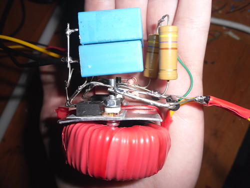
BTW I'm using this driver, not a ZVS... I guess a ZVS will kill it very quickly :/


Any tips to apply the electrical tape? Do I cut small sections or does it have to be uncut?
 
WOW that is a cramped Flyback, holy crud. I've never seen one like that before. I can understand your frustration now. New, high quality flybacks can be had for a couple dollars online, ask Le Quack for a source, or he may even have some left. I had him order several for things he made me. Lots of room in those and they work GREAT!

Re: electrical tape, you can cut it up, no problem. Just don't leave gaps.

Interesting circuit... a 555 driving what looks to be a push/pull which drives a single FET. I wonder if the fet's gate is getting the full 10V it needs. That neon light bulb there is very strange, I wonder its purpose, I would imagine to absorb the back EMF.... but still, odd indeed. Try varying the frequency of the 555 to hit the self resonance point of the primary... may not be doable since the capacitance will be super teeny. You could modify that design by adding a cap in parallel with the primary and setting the 555 to the resonant frequency of the primary LC tank circuit and get a major boost in output... but if you're arcing over it likely wouldn't be a good thing now anyway, haha.

Oh, btw, those knobs were for adjustment in OLD (but not super old where they used AC flybacks and multipliers) tvs. I'm not sure what they do to be honest.
 
Last edited:
The MOSFET will get whatever the supply voltage is; the purpose of the push pull stage is to increase the peak amp push into the mosfet's gate, preventing it from being in its linear region longer; basically reduces heating. :)

I actually don't have any of those flyback transformers left. The only ones I do have are relatively small.

That's odd that your flyback already arced over. I'd recommend putting it in oil. It helps dissipate heat, and also gets rid of arc over issues. It's just a little messy ;p

The Neon bulb is there to help absorb HV spikes during flyback operation. Is it needed? No, not at all, actually and removing it might even help with output. Hence, might.

The knobs are there to adjust a voltage divider inside of the flyback transformer. They adjust whatever their label is on the CRT which it used to power. They don't serve any purpose now, though! :)
 
Hi ,

Nice driver , you Can run that type of flyback via a ZVS , the limitation would probably be heat generation as a ZVS driver will produce a fair amount of output current from flyback .

on a very similar flyback to yours i was getting 8" arcs at 50 Volts supply I ran for 3 minuits Contiunuose and the flyback swelled and craked from the heat , but at lower voltages to ZVS and run and cool down times it would have probably lived alot longer

Id say try a ZVS even on 24 or 12 volts they are nice then if you dont like it , just go back to the driver you are using now :)

If anyone thinks his flyback wont stand ZVS'ness then just ignore me :D


Pic of Flyback on 50 Volts @ 10 Amps In .


Flyback on 50 Volts by TwirlyWhirly555, on Flickr
 
Last edited:
Yeah it's a pitty I only have this poor thing. If I'm going to spend I'd rather get an NST and try to build a SGTC, I've been wanting one for years... But that might be too hard at my current skill level :/

I agree adding more range to the frequency will help, it seems the resonance point is below the lowest frequency I get with that pot.

My driver is a bit different from the schematic, I skipped the neon bulb (Le Quack's advice) and the voltage regulator (I'm running on 12V anyways) and used a KSP42 instead of the MPSA42 (cause I couldn't find one here).

@Le Quack: I've read (on 4HV if I remember) that turning those knobs can reduce bottom pins arcing. Didn't really make any difference here.

Now my next step will be to add the electrical tape, replace the primary with insulated wire and see if I can reduce the arcing with more glue. If I can't the oil will be my only choice....

@ionlaser555: Wow, that's very impressive! Do you have schematics for that driver? I might try it if it comes down to using oil.
 
Last edited:


Back
Top