Welcome to Laser Pointer Forums - discuss green laser pointers, blue laser pointers, and all types of lasers

LPF Donation via Stripe | LPF Donation - Other Methods

Links below open in new window

ArcticMyst Security by Avery

Haaalp!

Kenom

0
Joined
May 4, 2007
Messages
5,629
Points
63
I need some electronics advice on some leadlights. I'm not going to waste the time posting particulars until someone tells me they might help me. suffice it to say the modules themselves work fine. it's a matter of finding out what's wrong with the boards. They have been modified quite a bit and I'm trying to fix them for someone.


Aseras

0
Joined
May 25, 2007
Messages
534
Points
0
stick them in a flatbed scanner and post some pics. we can fix them.
 

Kenom

0
Joined
May 4, 2007
Messages
5,629
Points
63
I have my camera fixed again (donno how many times I've had to pull that thing apart and tweak it) and it takes pretty good quality close ups. enough to see the boards. Instead of just pictures though I'm also going to show movies of the problems I'm having. This will explain better than words the problems I'm having. :)
 

Kenom

0
Joined
May 4, 2007
Messages
5,629
Points
63
Ok here's a movie of one of the one's I'm having problems with.
 

Attachments

  • Movie_003.wmv
    1.6 MB · Views: 44
S

SenKat

Guest
There could be a short, or a ground...two opposite issues. Take acloser look at the module, and see if any extra solder globs are hitting the barrell. make sure that everything that is supposed to touch the barrel is touching the barrel - and everything that is not supposed to be touching the barrell is not ! Make sense ?
 
Joined
Feb 1, 2007
Messages
810
Points
0
when connected to the external batteries, are you still driving through the board or direct to the diode assembly? If you are driving through the board then as Senkat said you either have a bad battery connection or something is shorting from the board through to the case. I am not very familiar with the leadlight , does it use a photo diode to regulate its current? If so, could an internal reflection on the inner casing be "Blinding" it and forcing it to drop current to the main diode?

Just some thoughts.

Jase
 
Joined
Jan 7, 2007
Messages
6,309
Points
83
It's almost like there's a bad battery contact at some place. Maybe between the cells. Also, have you measured the current with both configurations ??

Mike
 

Kenom

0
Joined
May 4, 2007
Messages
5,629
Points
63
I have not measured the current at both configurations as I have no clue how to do that.  Tell me or teach me how and I will.  

the leadlight does not use an APC no.

I've also checked for extra blobs of solder not where they are supposed to be and nothing there.  I will try the exact same batteries and see if that makes a difference.  It just could be the external resistance of the case is making it so that there is insufficient current going into the board.  I will also try cleaning (by filing) the contacts for the cap and whatnot.

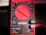
Here's my multi-meter.
 

Attachments

  • DSC00197.JPG
    DSC00197.JPG
    833.2 KB · Views: 106
S

SenKat

Guest
Kenom - are you SURE that is a multi-meter ? I saw that exact same item being marketed as a Laser Power Meter ! LOL !!!!!
 
Joined
Jan 7, 2007
Messages
6,309
Points
83
That meter is a dmm (digital multi meter) because there's a transistor tester socket. Any DMM can be a laser power meter with a calibrated sensor input.
The meter needs to be set up for measuring about 1 Amp of current. Probes from the cells to the body of the pointer. If you have the probes backwards, it will just say -x.xxx ..... Easy !!

Mike
 

Kenom

0
Joined
May 4, 2007
Messages
5,629
Points
63
EH? LPM? where can I get a head?? Ok so I hook one probe to the positive and the other to the body of the pointer. do I also connect the positive to the battery? I remember somewhere that I need to use the DMM as the wire to connect the power to read current as an extension if you will. connecting it in series. Correct?


Top