Welcome to Laser Pointer Forums - discuss green laser pointers, blue laser pointers, and all types of lasers

Buy Site Supporter Role (remove some ads) | LPF Donations

Links below open in new window

FrozenGate by Avery

gonna try a 375nm pointer build...

I seriously doubt the cornea fluoresces,

I don't know about the cornea, but the lens certainly does. While looking in the mirror, or enlisting the help of a friend, point a black light at your face. (365nm, none of that 395nm rubbish). You'll see this.

It doesn't cause color change in a laser dot, but it does cause a "haze" around violet/UV sources.

I wonder how many of the people tested got eye damage from UV?

The levels of harm and risk from everything depends on the dose. Ingesting 200 attograms of arsenic is harmless, while ingesting 200 grams of table salt is lethal.


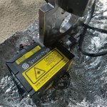
Got the unit in the mail today! Hopefully the diode isn't fried.

attachment.php


Can everyone see the picture in this post? I thought I read somewhere that I need to change some settings for attached pictures to be visible.
 

Attachments

  • 375.jpg
    375.jpg
    200.2 KB · Views: 167
I can see the pic no problem. Nice looking unit. :)
Hope it is ok as well.
 
Last edited:
Got the unit in the mail today! Hopefully the diode isn't fried.

attachment.php


Can everyone see the picture in this post? I thought I read somewhere that I need to change some settings for attached pictures to be visible.

Nice. Are you gonna fire it up before you tear it down?

The picture shows up for me.
 
Haven't really tried figuring it out yet, but I don't know how to power it up. Literally found zero info on the unit. If I can find an obvious method to power up the module I'll try it out, but otherwise it will get dissected.
 
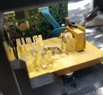
Tore down the unit enough to expose the diode, and stopped there. Inside the unit are a nice TEC and driver, as well as a collimating assembly, beamsplitter, and some small optics that are likely for beam correcting. One of the optics was loose in there, which may have been why this ended up on the surplus market. The diode is 5.6mm, and extracting it shouldn't be too awful (it is not press fit) but I don't want to yank it until I have enough time lined up to press it in a module and stick a driver on it. There's a good chance that will be tomorrow.

attachment.php
 

Attachments

  • sp375.jpg
    sp375.jpg
    121.7 KB · Views: 149
Honestly, the construction looks a little...
I was expecting optics mounted by means other than just glue.
I can't wait to see the rest.
 
Yeah the epoxy (probably UV curing glue) is a weakness but it isn't the first time I've seen it used when there are a bunch of tiny optics crammed together. Clearly this was aligned by hand, and may very well be a custom build where designing a bunch of mounts would be impractical. That UV glue is convenient for small optical trains...dab a little glue on the optic, take as much time as you need to get it in the right place, then hit it with a quick flash of UV and it is locked in place and you're ready for the next one.
 
That's a reasonable point. It just doesn't seem extremely robust.
I suppose in a laboratory or professional setting, where this is meant to be used, the device is expected to be fixed in place, so it wouldn't be an issue.
The problem I see with that is when setting up a complex series of optics, I'd expect that there would be some need to make adjustments and corrections as the optics are placed in the beam path. Using the glue, that might make it difficult. Oh well. Its good enough, apparently.
 
Sorry for sounding dumb, but may I ask. Why are there so many optics in there? Shouldn't it be as simple as the diode and a collimating lens slapped in front of it?

-Alex
 
Sorry for sounding dumb, but may I ask. Why are there so many optics in there? Shouldn't it be as simple as the diode and a collimating lens slapped in front of it?

-Alex

Could be for beam shaping/polarization adjustment or something else. More pictures would help us determine what they do.
 
So I was wrong about the diode mount, it IS press fit. About to spend the next hour or two filing...

The diode is 3 pin, not 4, so it must not be NDU4116 or NDU7216E like I guessed.

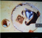
Here is the "2D code" printed on the back (What are these called again??) Is it possible to find a part number from this?

attachment.php


Sorry for sounding dumb, but may I ask. Why are there so many optics in there? Shouldn't it be as simple as the diode and a collimating lens slapped in front of it?

-Alex

For many applications you can't use the relatively poor beam characteristics of just a diode laser and a lens. The beam may need to be homogenized so the power density is uniform across whatever is being hit with the laser, or it may need to have a specific polarization. Beamsplitters can be added to sample the beam intensity for both power control as well as comparing to the fluorescence of a sample. Dichroic mirrors may be added to add/subtract other colors of light introduced from either fluorescing samples or other light sources. It gets complicated quickly!
 

Attachments

  • code.jpg
    code.jpg
    171.5 KB · Views: 132
My god Styro, don't tell me you're about to file all that down just to get the diode out. Let me know if you need a tool made, I've made and used one a few times for taking out 5.6mm diodes, though I can make one for any size.

I think those things are called QR codes. Nice to see some progress on the build. :D
 
Yes, that is a QR code. Whether you’ll be able to scan it and get any used information from it is unknown. The only way to find out is try.
 
Maybe tonight I'll map out the code by hand into PNG format and try looking it up.

Thank you for the offer ElectricPlasma...I actually have a 5.6mm extractor somewhere... can't find it though. Currenty filing away...if for some reason I can't extract it this way ill hit you up!
 
Yea Styro no problem, let me know if you need a nice host too, or if you've got a specific design in mind. Good luck on the filing though. :crackup:


Back
Top