Welcome to Laser Pointer Forums - discuss green laser pointers, blue laser pointers, and all types of lasers

LPF Donation via Stripe | LPF Donation - Other Methods

Links below open in new window

ArcticMyst Security by Avery

Get rid of your silicon battery blockers!!

cdanjo

0
Joined
Aug 28, 2007
Messages
29
Points
0
Hi folks!  Been watching this forum for a few months, but it's my first post!

Anyway, I'm working on a crazy Blu-Ray pointer circuit that I'll describe more later, but I wanted to share an idea with you DIYer's who are still using silicon diodes to protect from putting the batteries in backwards.  First some rants:
(1) Why are you using silicon??? It's got a lousy 0.7v drop, and we all know volts are valuable to a laser diode!  AT LEAST use a Schottky, like the cheap-o BAT54, which gives you a paltry 0.25v drop for a dime.
(2) Some people put the diodes in shunt with a drop resistor between the battery and diode - but then you lose voltage across the resistor!!!
Don't use diodes!!

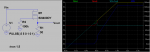
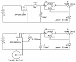
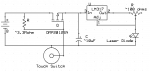
I propose the use of a p-channel MOSFET (for those with can-positive diodes, you can use the much more common n-ch MOSFETs).  I've just simlated one below.  I chose the DMP2012SN from Diodes, Inc. because it has BOTH a gate protection double-zener and a V_DS protection Schottly built in, so you don't have to worry about static frying the MOSFET!!  And it's a tiny SOT-23 package.
 To explain the simulation, I simulated the battery as a simple voltage ramp from -5 to +5v to show how it behaves even if the battery is backwards.  This voltage ramp feeds the drain-pin of the p-MOSFET and the gate is grounded.  Vin<0 corresponds to when the battery is backwards (the green and cyan lines in plot overlap for Vin<0 in the plot), and the output voltage, Vout (red line) is a nice 0v!  Note also the blue line is the current in the load resistor, chosen to be a hefty 30 ohms.  For Vin<0, there is no current flowing to your precious laser pointer.  
 The input voltage crosses 0v around 0.5s and still no output current.  That's because the gate voltage needs to be below the source voltage to turn on the p-FET.  Right around Vin=1v, the the turn-on threshold is reached and we start getting current.  Since this p-FET has an on-resistance (RDSon) of only 0.4 ohm, there is only about a 45mV (0.045v!!) drop from the battery to the load.  That's 10x better than Schottky and 20x better than silicon!!  It might cost you $1, but in my opinion, it's worth it.  BTW, you CAN find p-MOSFETs with RDSon of as low as 0.04 ohms or even less, I just wasn't patient enough to find any that also had both gate and D-S protection.

[The image is supposedly attached - I didn't figure out how to embed it yet]
Good luck and keep lasing!
 

Attachments

  • FET_sim.PNG
    FET_sim.PNG
    25.3 KB · Views: 264


cdanjo

0
Joined
Aug 28, 2007
Messages
29
Points
0
Forgot to add...

BTW, the cyan line in the figure is the voltage DIFFERENCE between the battery and load. We want that to be small and it is. Only 0.045v drop at 3v/100mA. :cool:
 

Benm

0
Joined
Aug 16, 2007
Messages
7,896
Points
113
Nice concept - this circuit is used as a low drop polarity protection for high currents as well, for example in solar battery chargers of serious power.
 

cdanjo

0
Joined
Aug 28, 2007
Messages
29
Points
0
Sample simple circuits:::

Below are some simple circuits you can build using this p-MOSFET blocker.  The top one is your conventional LM317T current source diode driver with a switch and p-MOSFET blocker.

The bottom one uses thep-MOSFET as BOTH a battery blockers and a TOUCH SWITCH (a la fancy Apple ipods/iphones)!!!  How cool is that?  Just epoxy a SINGLE electrode isolated from your grounded metal laser pointer housng, et voila!  It's also WATERPROOF and has NO CONTACTS to wear out!!  I tested the touch switch idea (on n-MOSFETs) and it seems very doable.  

Again, the MOSFETs are only a capacitor  when they are on or off in this configuration, so you won't drain your battery by leaving it hooked up like that.  
 

Attachments

  • SimpleMOSFETp_BatteryBlock.png
    SimpleMOSFETp_BatteryBlock.png
    27.3 KB · Views: 1,017

cdanjo

0
Joined
Aug 28, 2007
Messages
29
Points
0
SORRY BAD BOTTOM SCHEMATIC!!

The bottom schematic is WRONG -- SORRY! The 3.3M resistor should be on the battery side, not the regulator side. The below one is right.

Also, I'm not a big fan of the LM317T due to it's voltage drop and inflexibility. There are plenty of other great regulators that are much better. More details will come.
 

Attachments

  • SimpleMOSFETp_BatteryBlock_corr.png
    SimpleMOSFETp_BatteryBlock_corr.png
    15.4 KB · Views: 617
Joined
Jul 24, 2007
Messages
2,749
Points
0
I am liking the idea of a touch switch.......Do I take it that for the GB blues the circuit would need 9v input to cover the 3v drop on the LM317 ?

Regards rog8811
 

Gazoo

0
Joined
Jun 9, 2007
Messages
3,206
Points
38
Yes, and I am going to use a 9 volt battery. But I am going to use the 78L05A regulator only because I got them really cheap. These can very easily be used as current regulators. They are rated at 100ma's and come in a TO-92 case. Polarity protection is always optional. Since I will be using 9 volt batteries with their battery snaps, I really don't think polarity protection is necessary.
 

LarryQ

0
Joined
Aug 13, 2007
Messages
726
Points
0
The part number you have DMP2012SN crosses to a SMD at Digikey

Do you have a standard pin package part number for this Mosfet??

Looks good!!

I'm thinking it's time to warm up the soldering Iron!!

LarryQ
 
Joined
Jul 27, 2007
Messages
3,642
Points
63
just do a search for a P channel mosfet, even check ebay - it's often cheaper than ordering from digikey
 

Skram0

0
Joined
Aug 25, 2007
Messages
280
Points
0
Gazoo said:
Since I will be using 9 volt batteries with their battery snaps, I really don't think polarity protection is necessary.
In this case shouldn't polarity protection be required? One accidental 180deg twist of the 9v battery, then BAM! Dead. If it's even remotely possible to get reverse power on there, then I'd say go for the protection.


cdanjo said:
(1) Why are you using silicon??? It's got a lousy 0.7v drop, and we all know volts are valuable to a laser diode!
But Daedal's circuit doesn't suffer from a 0.7v drop, as it uses the silicon diode in parallel which has no drop.
 
Joined
Aug 3, 2007
Messages
342
Points
0
I like that, soft start power control!
A touch plate power switch. I like FETs too, because current and flaky mini buttons don't get along together well. Right, sparky fluttering lasers ?
Its similar to starter current going through a relay to battery so the starter switch can be low current.

I recommend:
Use a main switch on the battery if you use the touch option. Safety 1st.
I suggest use of a 1k to 100k value of resister between your finger plate (charged body bias the turns on the FET by voltage only) and the Gate lead on the FET.
(Or touch plate & use a switch and skip my 1k-10ok res.. mod.)
That’s because FETs are static sensitive over 90v. But it's not too critical because the FETs have internal static protection. Just might same eyes etc... if FET fails.


Note:
Shop for FETs that turn on with Gate voltage lower than 2.7. that’s Only %5 of the FET population. I bought bought dual SM fets. Only cost 5 cents more and have redundancy
double up.

DGM [smiley=beer.gif]
 
Joined
Aug 15, 2007
Messages
790
Points
0
Skram0 said:
[quote author=cdanjo link=1192825182/0#0 date=1192825164](1) Why are you using silicon??? It's got a lousy 0.7v drop, and we all know volts are valuable to a laser diode!
But Daedal's circuit doesn't suffer from a 0.7v drop, as it uses the silicon diode in parallel which has no drop.[/quote]

Maybe I'm missing something, but I think the diode parallel with the LD as reverse polarity protection has more like a 400V drop not .7V . At the voltages we're using it looks like an open circuit unless you connect the battery backwards, in which case it takes the full power from the regulator so that the LD doesn't see it.
 

Skram0

0
Joined
Aug 25, 2007
Messages
280
Points
0
a_pyro_is said:
At the voltages we're using it looks like an open circuit unless you connect the battery backwards, in which case it takes the full power from the regulator so that the LD doesn't see it.
Exactly. Like the pic below. No voltage drop, but reverse protection. Need to choose an appropriate resistor capable of handling the full load as a short across it, or just a beefy diode capable of handling the reverse current. If you can put the resistor directly across your voltage source and it doesn't get hot and burn, then it'll work. There's no voltage drop across the resistor either as the diode is not conducting with normal operation.

Although in thinking about this with the resistor, hopefully it wouldn't be too high a resistance so the voltage would pass through the circuit in reverse which may be the least resistance path. So possibly just a beefy diode capable of handling the reverse current would be best.
 

Attachments

  • diode_protection_001.gif
    diode_protection_001.gif
    7.8 KB · Views: 364

cdanjo

0
Joined
Aug 28, 2007
Messages
29
Points
0
Some replies...

Hi folks, thought I'd reply to a few remarks on this thread.

First of all, the silicon SERIES blocker will drop 0.7v.  You're right that a PARALLEL Si diode won't drop 0.7v from the battery to the diode.  Though I have seen some of you put a resistor in series with a battery and then a diode in parallel, which does drop voltage across the resistor!  The way Daedal does it is okay (best I've seen with a diode), as long as you don't mind possibly putting 0.7v accross your LD in reverse (probably ok).  If you have a strong source or a weak diode, I wouldn't rely on the parallel method to dump all the current, plus it will probably blow out your regulator.   What I was going for is something simple that acts BOTH as a protection diode with NO voltage drop and NO possibility of doing any damage if the batteries are reversed AND providing a touch switch, which I think is more reliable.

Skram0 (reply #13) -- DON'T USE THAT CIRCUIT!!!  If your 6v battery is reversed, you will have a 0.7v drop on the diode and a 5.3v drop on the resistor, but the FULL reversed 6v will still go to your precious LD!! (Assuming the battery is strong enough -- worst case).  Basically, I'd say MAKE R=0 ohms and you should be okay.  If the battery is reversed, the diode will short the battery but protect the LD (assuming the diode doesn't fry!).  

As for Laserrod's reply (#11), I agree that an extra ~100k resistor would be nice protection incase you give it a REALLY strong zap or if someone decided to hook the switch contact up to a battery, BUT, the gate capacitance of that p-MOSFET is like 10pF, so a 100k resistor would do nothing to the rise time, and the internal diodes will clamp it the same either way, so I will omit that 100k resistor on mine.  The gate diodes clamp it to +/-12v, which is way more than a pointer battery.
 Yeah, probably a power switch would be advisable if you're using the touch sensor on a 300mW DVD burner diode.  I won't use one on my blu-ray pointer.  I tested the touch switch on various materials (used socks, shirt pockets, foam, etc) and couldn't get it to light accidentally.
 You also don't need a "plate" but just a tiny wire contact, maybe 1x1mm is enough because of the lofty 3.3M resistor.
 BTW, that DMP2012SN turns on at only V(GS) = -1.5v, so there's no trouble turning it on.  I will be using a 2-cell supply and switch-mode voltage converter that will run down the cells about 2v.  Low threshold FETs are becoming far more popular with the rise of low voltage computers and hand held electronics.  I think the number of low threshold FETs is far above 5%.  Maybe 20% of the TO-220s, but if you go to SMDs, it's probably more like 50%.

LarryQ (reply #8) -- Sorry I only did research on SMDs!  I've been using the tiny buggers 80% of the time recently and I find them far more conventient than parts with leads, except you really can't breadboard with them!  I use simulations instead of breadboarding these days.   You can look up FETs on only website like digikey, mouser, allied, etc., or go to a manufacturer website, like Fairchild, Diodes Inc., International Rectifier, etc.  If you find a place that offers samples (most of them do, and TI is AWESOME for free samples and 1-day shipping!), you can get them delivered for free!  Just look for a relatively low-voltage FET (like 16-30v) that has gate protection diodes.  Preferably a low voltage threshold, like 1.5-2v.  Just about anything will work other than that.  You guys have to learn that you can get these parts for free!

As for current regulators, I'll tell y'all what I plan to use.  It's the TI TPS75105 LED driver.  Unfortunately, it only comes in one package style.  If you are afraid of SMDs, this will make you puke!  It's a 1x1mm Ball-Grid array with 9-pins!! (called a "YFF" package)  I had to tie two pins together in order to reach the center pin because ExpressPCB.com can only do down to 6-mil traces!  I'm still not sure how well I'll be able to solder it.  Hopefully well enough.  I routinely do SSOP-8's now, which were tough for a while.
 The TPS75105 the only ultra-low dropout (0.1v max) current regulator I could find that didn't require a floating ground (the BluRay diode is can-negative and my housing will be ground for the touch switches).  It's VERY easy to set the regulated current by a 0-200k resistor, and you can easily use Pulse-Width Modulation to control the brightness if desired.  Each unit puts out 0-100mA and they can easily be paralleled (especially at 1x1mm!).  Did I mention it's 0.1v dropout max??  And I got them for free??
 
Joined
Aug 3, 2007
Messages
342
Points
0
CDANJO,
I stand corrected, I was just generalizing.

Check out my NPN/FET string under General. Haven't got around to testing my dual FETs.
Got to try your FETs now. ;)
Thanks for sharing and welcome aboard.

DGM [smiley=beer.gif]


Top