- Joined
- Feb 12, 2016
- Messages
- 589
- Points
- 63
CDBEAM reported that the divergence of this 9mm red LD is awful and yes it is but since I have them I decided to combine (Alaskan, you asked someone to try this, here I am).
First subject was cooling: These red things like cold to perform and deadshadow has made a portable with TEC cooled P73 earlier. But TEC consumes power and most of all - produces heat, so to avoid fans and many batteries for TEC(s) I just decided to experiment with ice cooling like any chemist would.
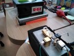
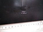
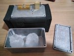
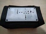
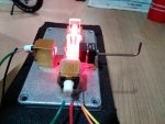
So I purchased an aluminium box with dimentions to fit two 5cm ice cubes (common bar size for drinks) and isolated its sides with armaflex foam. To use the lid (only 2mm thick but this is OK) as baseplate for combining.
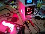
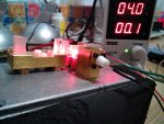
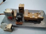
With 2 ice cubes in the box an LSP mount with Ushio inside kept cold at max 15-17ºC at 1.5A current - so during continous beaming there should be no moisture condensation on G-2 collimator lens.
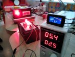
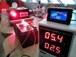
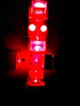
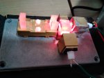
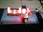
Then I added 2nd mount with LD connected in series, PBS and WP. The problem, however, was now moisture condensation on optics which do not have any "heating unit" like LD inside the brass mount. So I inserted 4mm cork board under optic mounts and it worked to delay moisture condensation significantly except for PBS cube mount where the screw position was not symmetrical and cork sheet under mount lead to instability. But OK with mecanics for now.
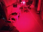
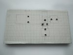
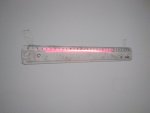
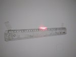
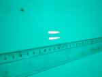
Then I adjusted beams directions to have 2 lines as a horizontal cross - can anyone say how to rotate LDs in these mounts in order to make spot lines really parallel???
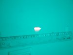
Added OL 6x pair of cylindricals to make lines 6 times shorter and noticed that there was no power at all in the beam!
The reason was that I made my setup as I have always done for blue NUBM44 LDs and it looks like red crystals are differently oriented than blue ones!!!
So the spots on wall I saw are just light passing through internal PBS mirror from which it should be reflected and the opposite.
The setup has to be rebuilt to have WP in the path of the straight beam and not the beam coming from the side!
Remarkably funny is that earlier I made the same (or oppositely same) mistake at design of the setup (now happily finished and working) to combine 4 blue LDs into a 16-20W single beam!
https://laserpointerforums.com/thre...aser-tank-gun-prototype-do-they-exist.100803/
First subject was cooling: These red things like cold to perform and deadshadow has made a portable with TEC cooled P73 earlier. But TEC consumes power and most of all - produces heat, so to avoid fans and many batteries for TEC(s) I just decided to experiment with ice cooling like any chemist would.
So I purchased an aluminium box with dimentions to fit two 5cm ice cubes (common bar size for drinks) and isolated its sides with armaflex foam. To use the lid (only 2mm thick but this is OK) as baseplate for combining.
With 2 ice cubes in the box an LSP mount with Ushio inside kept cold at max 15-17ºC at 1.5A current - so during continous beaming there should be no moisture condensation on G-2 collimator lens.
Then I added 2nd mount with LD connected in series, PBS and WP. The problem, however, was now moisture condensation on optics which do not have any "heating unit" like LD inside the brass mount. So I inserted 4mm cork board under optic mounts and it worked to delay moisture condensation significantly except for PBS cube mount where the screw position was not symmetrical and cork sheet under mount lead to instability. But OK with mecanics for now.
Then I adjusted beams directions to have 2 lines as a horizontal cross - can anyone say how to rotate LDs in these mounts in order to make spot lines really parallel???
Added OL 6x pair of cylindricals to make lines 6 times shorter and noticed that there was no power at all in the beam!
The reason was that I made my setup as I have always done for blue NUBM44 LDs and it looks like red crystals are differently oriented than blue ones!!!
So the spots on wall I saw are just light passing through internal PBS mirror from which it should be reflected and the opposite.
The setup has to be rebuilt to have WP in the path of the straight beam and not the beam coming from the side!
Remarkably funny is that earlier I made the same (or oppositely same) mistake at design of the setup (now happily finished and working) to combine 4 blue LDs into a 16-20W single beam!
https://laserpointerforums.com/thre...aser-tank-gun-prototype-do-they-exist.100803/


")