Welcome to Laser Pointer Forums - discuss green laser pointers, blue laser pointers, and all types of lasers

LPF Donation via Stripe | LPF Donation - Other Methods

Links below open in new window

ArcticMyst Security by Avery

FREE DIY open source BOOST driver!!! Tested & working!!

tony1

0
Joined
Jan 4, 2012
Messages
54
Points
0
Snowluck,

One look at it tell me the work is done in a hurry. Very poor workman ship, unskilled work.
Watch some videos in u tube. You can use a suitable iron to do the work. It will be messy to unsolder and try again. Start a new , one component at a time. Use a bare minimum Paste and solder. There appear to be many shorts.
good luck.


Joined
Aug 30, 2008
Messages
6,891
Points
83
You can also use paste and stick an iron on the heat sink pad to reflow it all. This will let you monitor the process and move any components while the solder is melted if needed
 
Joined
Oct 18, 2013
Messages
1
Points
0
Long time lurker, first time poster....

I want to combine two of the mini's onto one PCB, with one set of input and output tabs. What components (if any) could I make common?

I'm assuming the external FET is for reverse polarity protection so there's that. What about the output capacitors? Input Cap?

Any advice would be greatly appreciated :)

- Matt

EDIT: Oh, and is there any particular reason why such large SMD components were used? I would like to use all 0603 parts where applicable and I figure provided they have the same specs everything should work fine?
 
Last edited:
Joined
Apr 6, 2013
Messages
30
Points
0
I am having an odd problem, the driver works, however it outputs 300ma nomatter what value sense resistor I use. Has anyone ever herad of this before or seen this?
 

rhd

0
Joined
Dec 7, 2010
Messages
8,475
Points
0
I am having an odd problem, the driver works, however it outputs 300ma nomatter what value sense resistor I use. Has anyone ever herad of this before or seen this?

What's your input power source?
What are you driving? (if a test load, what is the configuration)
Where is the driver from, did you reflow it yourself, or purchase it?
 
Joined
Apr 6, 2013
Messages
30
Points
0
My input power source is a 18650 cell at 4.1v

I'm driving an M140 Diode.

I reflowed it myself. I did a much better job this time than the one I posted here a year ago. I used a metcal hct2-120 hot air reflow station.
 

benmwv

0
Joined
Sep 10, 2010
Messages
1,380
Points
48
Care to post a picture of the full setup? Although it sounds like a damaged lm3410 to me :(

Is this the sot-23-5 or the llp 3x3 version?

Try checking continuity between the Vin and LD+, if you get low R that's the problem.
 
Last edited:
Joined
Apr 6, 2013
Messages
30
Points
0
It's the llp3x3

Thats unfortunate if that is the case, that's my last one in that package.

I left it at the lab, I'll foe back later tonight or tomorrow.

Low resistance means it's the lm3410?
 
Last edited:

benmwv

0
Joined
Sep 10, 2010
Messages
1,380
Points
48
If there is low resistance there power is just shooting through like no driver is present. Either because a blown chip or a short beneath the chip. You should try removing the IC the reflowing it again. If that doesnt work and you are sure there are no other problems then you will need another lm3410.

Correctly reflowing the llp 3x3 by hand is no small feat, it takes practice and preferably a solder paste stencil. You can check out OSHstencils I've heard they are good and cheap.
 
Joined
Apr 6, 2013
Messages
30
Points
0
It is boosting the voltage so I assume that means that the driver is doing something.


I will look into Oshstencils. Depending on how long their shipping is I might just try making my own on a lasercam.

I can post pictures like you asked to show how the rest looks and see if there are any problems I missed that you might catch.
 
Last edited:

rhd

0
Joined
Dec 7, 2010
Messages
8,475
Points
0
It is boosting the voltage so I assume that means that the driver is doing something.

It might not be boosting. If the IC is dead and the battery is in a direct drive connection to the diode, the diode might lase. If memory serves (it has been a while), the voltage of a full li-ion is sometimes enough to drive a 445 at low power. This would also explain the non-impact of resistor value changes.
 
Joined
Oct 6, 2014
Messages
30
Points
0
Hey guys,

Has anyone used the BenBoost Mini inside a C6 Host? If you have would you mind sharing how you went about that?

I'd like to use the mini in my C6 M140 build but don't know if it's worth thr trouble compared to just using the round one instead (without OVP).

Thanks, Nelly
 

rhd

0
Joined
Dec 7, 2010
Messages
8,475
Points
0
Necro post with a purpose - This is just a brainstorm. Is there any reason we couldn't add a MOSFET, with gate tied to the SW output on the LM3410, as a way of effectively bypassing the limitation of the internal switch (by not using it)?

I'll have to brainstorm on this for a bit, but this is what I had in mind. EDIT: modified since initial posting.
attachment.php


Looking at the datasheet diagram, there's an internal current sense on the output of the NMOS that we'd be bypassing. I don't think that matters because my guess is that it's just there to protect the NMOS, so the lack of substantial current across it shouldn't be an issue.

I think the external MOSFET needs to be a P-MOS in order to make the switching cycles work as expected, but I may be backwards on that. The example above would be an attempt to boost to 1.6A, which the LM3410 can't typically do otherwise.
 

Attachments

  • example.png
    example.png
    8.5 KB · Views: 223
Last edited:

benmwv

0
Joined
Sep 10, 2010
Messages
1,380
Points
48
I've thought about that before, actually I think I might be able to dig up a .brd of it on my old laptop from like 2 years ago. I'm pretty sure there is a data sheet (I dont think its was lm3410 specifically, but same idea) that has a mosfet in one of the designs to extend the range and I basically modeled after that. I'll try to find it.

Anyways, two things in your design there I think need to be changed for it to work.
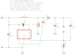
1. Move the pull up resistor to the Vin (before the coil) so crazy spikes and ripple aren't running into the gate of the fet.
2. Change it to a 100 ohm. Because of how fast the device switches I'm 99% sure the 1M resistor won't let enough current through to saturate the gate quickly, resulting in it operating in the linear region (where it has not high, but not its lowest resistance either) majority of the time. Basically it will be trying to pass large amounts of current while it is very slowly (relative to the operating frequency at least) moving to its minimum resistance and when it's somewhere around order of 1ohm it will be burning so much power the thing will worst case pop, best case be wildly inefficient and low output. A 100 ohm resistor should be low enough to let it open quickly and efficiently while still only leaking like 40ma when it's connected to ground by the internal fet.


Also @ nelly little late, but yeah you can make a nice and cheap laser if you pop an m140 and a mini drive set to like 1.25A in c6. You'll get long runtimes, reliable, and enough power to wow all your friends. Just make sure you get some laser safety glasses.
 

rhd

0
Joined
Dec 7, 2010
Messages
8,475
Points
0
If you find that circuit, let me know. But if not, I may toss something together and try it.

Other than your notes above, does my logic that it needs to be a P Mosfet, with Source connected to ground, make sense?


Top