Welcome to Laser Pointer Forums - discuss green laser pointers, blue laser pointers, and all types of lasers

LPF Donations

Links below open in new window

ArcticMyst Security by Avery | Browser Hide by Avery

FREE DIY open source BOOST driver!!! Tested & working!!

rhd

0
Joined
Dec 7, 2010
Messages
8,475
Points
0
Just a friendly heads up...
Inductors are measured in Henrys... (uH in this case)
Capacitors are measured in Farads... :beer:

Units were wrong, numbers were right. I constantly write uF instead of uH, and sometimes vice versa.

That said, it's a pretty safe mistake. You won't be able to find any 10uH capacitors on Digikey ;)


Joined
Sep 20, 2008
Messages
17,640
Points
113
N/P... it was meant more for the Electronically challenged
to not confuse them....:D

Jerry
 
Last edited:

benmwv

0
Joined
Sep 10, 2010
Messages
1,380
Points
48
Foulmist, I think if you stack that 22uf you removed on top of the Vout/GND cap it will bring the ripple back down.

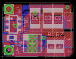
I have the latest board file for the DFN version attached. It is using 2x 22uf output caps.
attachment.php
 

Attachments

  • benboost mini.png
    benboost mini.png
    30.7 KB · Views: 551
  • LD Boost Driver lm3410 LLP3x3 v5.zip
    34.2 KB · Views: 73

rhd

0
Joined
Dec 7, 2010
Messages
8,475
Points
0
Dumb Question, are the inductors in the parts list ok at 1.6 MHz?

NR8040T100M Taiyo Yuden | 587-2001-1-ND | DigiKey

This is *REALLY* taxing my understanding of things - so if someone else says otherwise, trust them.

The inductor we went with (like many inductors) was tested at a frequency of 100 Khz, and had a self-resonant frequency of something like 20 Mhz. My understanding is that this means the 10uH rating was the inductance measured when tested at a frequency of 100 Khz. The inductance will decrease as you move towards the 20 Mhz mark. At that point, I think the inductance actually flips - becomes negative. But if I'm understanding correctly, the important part here is to understand that 1.6 Mhz is a lot closer to the 100 Khz end of the scale (the end at which inductance is 10 uH), than it is to the 20 Mhz end (the end at which inductance is 0). I don't know if the relationship is linear, or exponential, but I would imagine that either way, 1.6 Mhz implies a true inductance for our purposes of just slightly below 10 uH.

The above ^ may be totally inaccurate.
 
Joined
Dec 27, 2011
Messages
2,062
Points
48
The reason I asked is that I was looking at these...

http://www.vishay.com/docs/34299/lp12ab11.pdf

I noticed that it said,

• Frequency range up to 1.0 MHz

That got me to wondering if the one in the parts list had a range and if we were beyond that range... I'm out of my element too.


I think that you are correct. I skimmed this and it appears correct anyway,

Self Resonant Frequency

^^^ PDF ARTICLE ABOVE ^^^
 
Last edited:
Joined
Dec 27, 2011
Messages
2,062
Points
48
http://www.vishay.com/docs/34250/ihlpap.pdf

The IHLP inductor is constructed using an “open” or “air coil” inductance coil. The two ends of the coil are connected to a lead frame that acts as a means of transport through the manufacturing operation at Vishay, and as the final termination pads when the part is singulated from the lead frame.

A powdered iron core is pressed around the inductor coil after the inductor coil is welded to the lead frame. The characteristics of the powdered iron enhance the magnetic properties of the inductor and also give the inductor its final shape or footprint


GOOD SLIDESHOW on new inductor technology...

CLICK HERE FOR SLIDESHOW

^^^ SLIDESHOW ^^^
 
Last edited:
Joined
Feb 7, 2012
Messages
977
Points
0
I just tried another triple build with no luck so I am giving up on that. maybe it has something to do with them being the OVP boards. These were lower 633ma stand alone they can almost run constant unheatsinked combined they get super hot in seconds. I havent had any luck whatsoever paralelling any of these OVP boards.
 
Joined
Feb 7, 2012
Messages
977
Points
0
Doh on to inductors I use the one in the op but I also Used the round inductor for the round boards... Maybe the round inductor had something to do with the round boards testing.
 
Joined
Mar 29, 2011
Messages
1,056
Points
48
Foulmist, I think if you stack that 22uf you removed on top of the Vout/GND cap it will bring the ripple back down.


Ben, 22uF is pretty enough I guess for the ben boost.

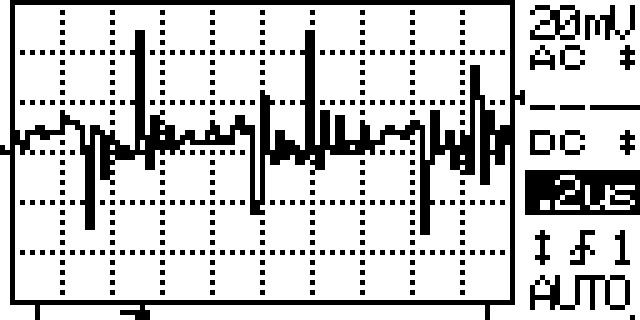
I just stacked the other 22uF on top of this one making the output cap 44uF as you mentioned. See the results:


44uF Output Cap
125A44uFbenboostripple.jpg


compared to 22uF output Cap

benboostnocapripple.jpg


Just what I expected. The extra cap did absolutely nothing.
The ripple is the same with just one 22uF cap...
 
Joined
Dec 27, 2011
Messages
2,062
Points
48
Am I reading that wrong? It looks like the 44 uF is lower? No? Not much mind you, but lower?
 
Joined
Mar 29, 2011
Messages
1,056
Points
48
Am I reading that wrong? It looks like the 44 uF is lower? No? Not much mind you, but lower?

actually the position of the waveform on the screen is a little lower than Zero that's why you read it wrong if you count the dots you you will see that is practically the same :D


Top