Welcome to Laser Pointer Forums - discuss green laser pointers, blue laser pointers, and all types of lasers

Buy Site Supporter Role (remove some ads) | LPF Donations

Links below open in new window

FrozenGate by Avery

FREE DIY open source BOOST driver!!! Tested & working!!

Oh, it's toast. I broke the inductor trying to measure the set resistors with my meter. I was pressing down trying to get a firm contact and it slipped off and cracked the inductor.

I'm writing it off as a learning experience.

I think that I have a couple more that I can abuse.

Assuming lowering the voltage to the proper level works ;) then how do I get a scope on it? Is it as simple as connecting the scope across the 1 ohm resistor?

BTW, you are right. The test load does get warm very fast at 750mA. :D


Brainfart. Yes I know that. Yes I overlooked it. Thanks for reminding me. ;)

Sometimes I hate to even ask for help fearing that I will be pounced on for even the simplest mistake. Glad to see that is not the case. :)

Normally I try to be a lot more graceful / forgiving. But in this thread, after all the alarmist bell-ringing that "something was wrong" with the driver, not so much. Tact is not a concern for me in this thread ;)

We get people measuring voltage drops wrong with DMMs inline with the driver output, configuring their test loads incorrectly, and powering the boost driver as if it was a buck, yet it's the driver that must be to blame when a diode dies, not user error...... ;p
 
Last edited:
Normally I try to be a lot more graceful / forgiving. But in this thread, after all the alarmist bell-ringing that "something was wrong" with the driver, not so much. Tact is not a concern for me in this thread ;)

We get people measuring voltage drops wrong with DMMs inline with the driver output, configuring their test loads incorrectly, and powering the boost driver as if it was a buck, yet it's the driver that must be to blame when a diode dies, not user error...... ;p

That's nice.

Does anyone know how to scope it? Is my theory correct? Can I look at V across the resistor and expect to see a ripple that echos the current ripple. I'm stupid, so I may be way off base here. ;)

Honestly, it's no big deal. I hate looking stupid but when you screw up, you screw up. I don't think forgetting that this was a "one battery driver" for a moment qualifies me for the Special Olympics though.

My biggest concern is that people could start to try and hide mistakes or errors in fear of being ridiculed instead of being open about things in an attempt to help out.

Heck, the only reason I am doing any of this is in an effort to get to the bottom of the situation in the proper manner.

My personal opinion (don't forget, I'm stupid so this may be wrong) is that it is probably as simple as going from 10uF to 22uF on the caps. But I don't know and I'd like to be a part of the solution. But I'm new to a lot of what I am doing and like any hobby or skill that you do for the first time, things that are second nature to someone who is experienced are items that are easily overlooked by the beginner. I need a checklist to make sure I don't miss something simple.

You get a dozen things right, but it only takes one thing wrong to make you look foolish. :)
 
My biggest concern is that people could start to try and hide mistakes or errors in fear of being ridiculed instead of being open about things in an attempt to help out.

Yep, that's a valid concern. I share that concern as well.

My personal opinion (don't forget, I'm stupid so this may be wrong) is that it is probably as simple as going from 10uF to 22uF on the caps. But I don't know and I'd like to be a part of the solution. But I'm new to a lot of what I am doing and like any hobby or skill that you do for the first time, things that are second nature to someone who is experienced are items that are easily overlooked by the beginner. I need a checklist to make sure I don't miss something simple.

Nobody has demonstrated to me that there actually is a problem, so I dislike trying to speculate as to the cause of an effect that hasn't yet been demonstrated.

Of course, "lack of evidence" is not the same as "evidence of lack". So I eagerly (and openly) look forward to your findings with the scope!
 
Does anyone know how to scope it? Is my theory correct? Can I look at V across the resistor and expect to see a ripple that echos the current ripple. I'm stupid, so I may be way off base here. ;)

I don't have a scope, but that sounds right to me.
 
Oscilloscope Frequently Asked Questions

Can I measure currents with an oscilloscope?

Yes, there are two ways to measure a current with an oscilloscope.

1. The simplest way is to add a resistor in series with the current you are trying to measure, and then divide the voltage shown on the oscilloscope by the resistance to determine the current.

2. A much more expensive way of measuring current is to use a current probe. Current probes are basically a loop that goes around the wire that has the current you want to measure. They inductivly couple the current signal for measurement for an oscilloscope.

Current probes are only good for spikes or AC current. They're also made of Current transformers. Relatively simple to make.
 
I think that I got a scope on this. I will try to post more tonight, I did a video and some pics.
 
You must be doing it wrong like I do!!! Learn from misteaks!!! I wish I could help you.. what kind of scope did you buy? will it measure that low? I duno things I might think about... I know nothing about scopes.. But it isnt showing up for me either..

RHD you could be alot more helpfull if you wanted to be.. I would rather pick your Brain than hear your echo's taunt us in the middle of the night... I would love to hear some real input from you into this. Yes were a bunch of n00bs maybe not as smart as you but you have to be understanding of that and if your not then I suggest you bugg out and let us hash this out.. If you want to be nice and jump in to tell us what were doing wrong then fine but I really have had enuf of the crap..
 
Guys, I am out of town right now so I am not able to do this right now. I will as soon as I can. Sorry! I thought that I would have some spare time but so far I haven't.
 
Ok, quick upload of pics. I'll do video later but all it shows is that the first pictures are truly a "first few moments of startup."

I was pretty excited to get it to work. I figured out how to set the trigger for the first instant of positive voltage and turned it on and actually saw it draw the line.

I think that I need to change the timeframe to record more time though. I think that I only got the first part of the waveform so I'm thinking I need to do a longer amount of time on the graph.

Started with a Moh Benboost at 478mA

Dialed in about 4 volts. :P


Untitled by tsteele93, on Flickr

It works.

Hooked the scope (Tek TDS210) to it, plugged in the positive side of the PSU and it drew out this waveform...


Untitled by tsteele93, on Flickr

Here it is on measure mode.


Untitled by tsteele93, on Flickr

Here it is at higher sensitivity


Untitled by tsteele93, on Flickr

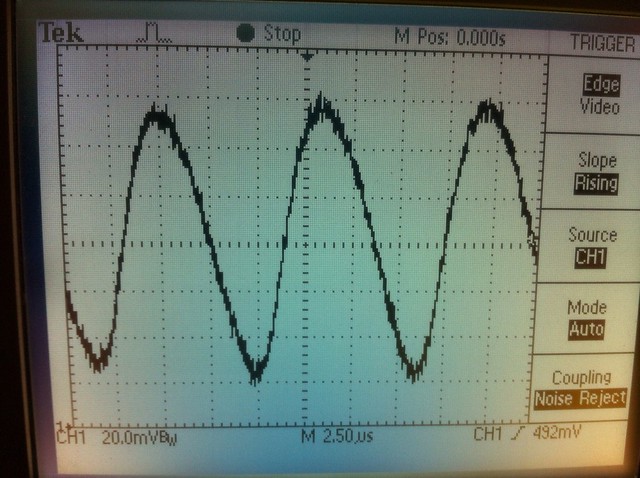
Here are some shots of it after the startup with it just running. I think the next three are all the same snapshot with different resolutions on the x and y axis.


Untitled by tsteele93, on Flickr


Untitled by tsteele93, on Flickr


Untitled by tsteele93, on Flickr

Again, I apologize. We are on a trip in the mountains and I thought that I would have time to do this last night but I was wiped out and laid down and fell asleep as soon as my head hit the pillow. I drove five hours then we hiked for two hours so I am tard.

When I get back, I'll record a long video of testing so everyone can pick it apart and see if I am doing something wrong or if there is something that can be figured out by seeing the actual testing. For now, I'm off to hike to the bottom of Fall Creek Falls in TN.
 
Last edited:
RHD you could be alot more helpfull if you wanted to be.. I would rather pick your Brain than hear your echo's taunt us in the middle of the night... I would love to hear some real input from you into this. Yes were a bunch of n00bs maybe not as smart as you but you have to be understanding of that and if your not then I suggest you bugg out and let us hash this out..

It has nothing to do with "smart" or "noob". Those are silly words that should have no application here. The issue I had was with how this concern was approached, particularly by guys like RyanElectron, who posted big glaring "warning" signs.

When there are members with experience, with properly reflowed boards, having only success with the drivers, and then members with relatively less experience, and unknown-quality assembled boards, having trouble, the logical conclusion is not that the design is faulty, but rather that the components / assembly / usage of the problematic fork of the drivers was.

But that's not how it was presented by guys like Ryan, IE, someone who popped up to financially capitalize on other peoples efforts, then criticize those efforts, and give nothing absolutely nothing back in the process. That's the behavior that I found particularly irresponsible and disrespectful, and to be frank, just downright slimy.

On an interesting note, the scope output that TSteel has posted looks a whole lot different (worse) than the output I remember seeing from my drivers. TSteele has a *much* better scope than my little DSD Nano, but assuming my scope wasn't just failing life, this would seem to lend some credence to the notion that the use of 22uF caps was beneficial.

EDIT: Wait a minute! Am I totally failing at math, or does that output ripple look like 525 kHz? If so, that would definitely shed some light on the issue.
 
Last edited:
rhd I think it's 1.6MHz :D

anyway that looks like a HUGE spike on startup doesn't it? :D
 
rhd I think it's 1.6MHz :D

anyway that looks like a HUGE spike on startup doesn't it? :D

Is it? Step me through the math on that. I'm sure you're right.

I think it's a huge ripple pictured, but not really a startup spike, because isn't that just during normal operation? He said that those last three were the same shots, but "after" startup, which I would take not necessarily to mean a startup spike, but rather just the ongoing ripple. (which is just as bad)
 
Last edited:


Back
Top