Hey guys sorry fr not having answered all this time... I was on holidays and all that stuff....
As I promised here's the schematic/PCB design/parts list for the driver described in this post.
Parts list:
FOR SINGLE LI-ION CELL WITH BUILT-IN BATTERY PROTECTOR:
-1x MAX1723EZK+ ---> sample it here
Ordering Info - MAX1722, MAX1723, MAX1724 1.5µA IQ, Step-Up DC-DC Converters in Thin SOT23-5
-1X TPS3808G33 ---> sample here
Power Management - Supervisory Circuits(Voltage Supervisors) - TPS3808G33 - TI.com
-2X 10uF 0805 X5R capacitors. No samples for these ones, I have like 15 in stock, if you REALLY need some I can send you two for $3 + shipping
-1X 12 ohm 1/4W 0805 resistor (that's the current sensing resistor, i'll explain later how to calculate the value for higher or lower current)
-1X 10uH SMD inductor. I use these ones that you can sample:
Free sample request(there are smaller ones but these were the first ones I found)
-1X 10Kohm 0805 resistor
FOR THE 1.5V AAA VERSION (NOT GUARANTEED TO WORK WITH 1.2V RECHARGEABLE CELLS):
-1x MAX1723EZK+ ---> sample it here
Analog, Linear, and Mixed-Signal Devices from Maxim/Dallas Semiconductor
-2X 10uF 0805 X5R capacitors. No samples for these ones, I have like 15 in stock, if you REALLY need some I can send you two for $3 + shipping
-1X 12 ohm 1/4W 0805 resistor (that's the current sensing resistor, i'll explain later how to calculate the value for higher or lower current)
-1X 10uH SMD inductor. I use these ones that you can sample:
Free sample request are smaller ones but these were the first ones I found)
-1X MBR0530 Schottky diode in SOD-123 package. Again, no samples. I have like 40 of these, if you want one it's $1 + shipping
Schematics:
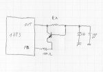
These are done with paint from a schematic found in MAX1723 datasheet:
FOR LI-ION VERSION:
FOR 1.5V version:
PCB DESIGNS:
drivera.pcb is for the li-ion version. 2 layers PCB.
driverb.pcb is for the 1.5V version, 1 layer 0,8mm PCB, solid diode mounting system. Be careful not to make solder bridges and solder the case pin FIRST. When you test that it's firmly attached, solder both + and - pins through the holes. 0,5mm tip soldering iron required. Case pin provides negative contact.
I have yet another PCB design, as small as driverb but for LI-ION version. It's the one you can see in the second set of pictures i posted. I'll upload it later as for some reason i can't find it in this computer... (i thin i overwrote it, but I have a copy on the other computer)
Soldering paste and hot air gun is recommended for soldering both drivers.
Feel free to modify them in any way, although they are very compact and the layout has been carefully made following manufacturers recomendations to avoid electrical noise problems.
designs are attached.
HOW TO SET THE CURRENT:
With a 12ohm resistor this driver will give you 100mA. If you want more or less, up to 150mA, use this formula:
Resistor value (in ohms) = 1,235/Current in Amps
For example, for 150mA you would require a 8,2 ohm resistor
HOW THIS DRIVER WORKS:
It's easy: the switching IC is designed to provide constant voltage. it has a feedback pin whith a fixed voltage, in this case 1,235V, used to chek the output voltage.
According to ohm's law, voltage drop in a resistor depends on the current that goes through them. So, when the current through the diode passes through the sensing resistor, it makes a voltage drop... that will be exactly 1,235 V... and if not, the IC will try to stabilize it... and the unic way it has is to vary the current to a value that, passing through the sensing resistor, would make a 1,235V voltage drop.
The battery protection feature uses a voltage supervisor IC, that detects if the voltage drops below 3,07V (3.7V li-ion cells shound't be discharged below 3V) and 20 milliseconds later pulls its reset line to ground. So, we connect the reset line of the supervisor to the shutdown line of the switching driver. If the shutdown pin of the driver is grounded (low state) the driver shuts down, drawing just a few uAmps from the battery. There are more TPS38G08 series IC designed for other voltages.
I found another interesting current driver IC at Texas Instruments that would allow for electronically programmed current (rather than turning a pot) and PWM dimming and all stuff like that. It would require a microcontroller and their features would "depend" on its program. It would allow up to 1200mA at 5.5V. No more than 5.5V as it's a constant current driver circuit designed for white LED's. It would also require isolated casing as there won't be common gruond or common positive. The PCB is designed but as always.... no time for further developing as I'm on holidays having as much fun as I can until university starts. I think that from now on i'll just release all the work i do for free under creative commons non commercial license.


