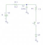
I just got one before the price drop. I took it apart and traced some of the power circuitry. The circuit is basically a op amp / PNP transistor current regulator. The attached circuit shows the power stage.
The 6.2 ohm resistor and 220uF capacitor slow down the batteries' dV/dt when the switch is closed and helps to eliminate the initial current spike that can typically happen with this type of current regulator. The problem is the voltage drop across the 6.2 ohm resistor. With my batteries, the voltage applied to the circuit is about 5.5 volts at about 270 mA. With 270 mA there is a 1.67 volt drop across the 6.2 ohm resistor which leaves 3.83 volts to power the regulator circuit (5.5 - 6.2 x .27). The sense feedback resistor is 1.5 ohms which drops another 0.41 volts (.27 x 1.5) leaving 3.42 volts to power the LD and the Vce for the PNP transistor. If the LD drops about 3 volts at 270 mA then there is about 0.42 volts across the PNP transisor which puts it in saturation and unable to regulate the output current. In order for the regulator to work the voltage needs to be higher.
To get more power from mine, I simulated the circuit and compared data from varying the supply voltage and measuring the conducted current. After I got agreement, I simulated a 10 ohm resistor in parallel with the 6.2 ohm resistor. Then I soldered a 10 ohm resistor in parallel with the 6.2 ohm resistor. Now my current is about 340 mA and burns much better.


