Welcome to Laser Pointer Forums - discuss green laser pointers, blue laser pointers, and all types of lasers

Buy Site Supporter Role (remove some ads) | LPF Donations

Links below open in new window

FrozenGate by Avery

DIY Laser Torch

Daedal said:
Well... I did say that I used the TO-92, but I also did say that it's only rated up to 100mA.  :(

I changed the first post after that last reply so that it won't be a source of anymore confusion.  ;)

--DDL

:D yeah, but it is working fine in your MXDL, so maybe the ones having trouble fitting their regulators into the ring, can also use the TO-92. But that would be still a littlebit risky...


thanks for all your help Daedal and the only thing i really changed was soldiering the washer directly to the laser housing. works great :)
 
pieces said:
thanks for all your help Daedal and the only thing i really changed was soldiering the washer directly to the laser housing. works great :)

You're very welcome :)

I'm glad I could help ;)

--DDL
 
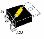
If you want to use the bigger LM317 you could try what I have done.

Cut off the heatsink tab and the middle pin, fold the outer legs under and cut to length.  Then mount the resistor between adj and out by soldering to where you cut the heatsink off.

It will now fit a much smaller space.....

(In drawing cut off heat sink is shown with dotted line).

Regards rog8811

*Thinking about it I may have bent the legs the other way to get the resistor between the PCB and the LM, but either way it saves space.....*
 

Attachments

  • lm317_space_save_001.jpg
    lm317_space_save_001.jpg
    27.2 KB · Views: 278
WOW..Nice idea!!!
I had no idea that the heatsink would work as the adj input!

So....

Would it be possible to put a Pot on top of the 317 either instead of a fixed resistor or in addition.

I like the idea of putting the resistor Under the 317 as well!!!


It would be nice to be able to adjust the current!

Larry
 
I have the DX 5mw LED flashlight, the reg and resistors ( 2X10R in my case) fit perfectly into the aluminium housing that held the LED. it leaves plenty of room up front for the rest of the gubbins.....In fact with the next one I make I am toying with fitting a pot for external adjustment..... all I need now is my next batch of GB reds....

Regards rog8811
 
Oh...wait a min...

The heatsink is the voltage out ...correct>????

So you would also need to connect the heatsink area to go to the LD.

Is this correct????

Larry
 
Strange as it seems LD connects to adj just as Gazoo says, look at DDL's circuit, page one on the driver sticky.

Regards rog8811
 
rog8811 said:
Strange as it seems LD connects to adj just as Gazoo says, look at DDL's circuit, page one on the driver sticky.

Regards rog8811

If i am correct, that was a little ::) mistake DDL made in his scematic. correct me if i am wrong, but i thought i red about it somewhere.
 
The heatsink is the Vout... also... the Resistor would get hot in that configuration and heat up the LM even further... lowering efficiency and operating current... :(

--DDL
 
Hi DDL, unless I have missed something along the way, the output goes through the 5R resistor but in effect is connected directly to the adjust as per your diagram (repeated below).

I agree with you about the heat but I was limited for space in the circuit housing....it will be a bit of suck it and see I guess..........you have done a lot more with both the circuit and the LD's, with a 5R resistor how quickly does it warm up and have a noticable effect on output?

Regards rog8811
 

Attachments

  • DDL_circuit-cutdown.jpg
    DDL_circuit-cutdown.jpg
    114.7 KB · Views: 4,535
If a single 5 Ohm resistor is used, will a 1/2 watt be large enough??

I'm seeing the need for at least 1 watt given 3 volts and 300 Ma as high numbers.

If I need 1 watt, I will need to wind (2) 10 Ohm 1/2 watt Resistors together, and that will take up more room.

I am going to try and run the resistor along the side of the LM 317 just to keep it off the "Face" of what is left of the heatsink.

Larry
 
I have 2 X 10R 1/2 watts side by side under the reg, still makes it very low profile, I would not have had room to put them alongside....

Regards rog8811
 
Larry,
I believe you're forgetting about the voltage drop of the LD. The resistor shouldn't see 3V just the 1.25V between Vout and Adj. pins. So 1.25 x .300A = .375W a .5W should be more than enough for any of the 16X DVD burner diodes. Even if they're TECed.
 
Given 5 ohm and 6 volts in...once thru the LM 317.
I plaved the stock diode that came with the MXDL as a test..

I am seeing 150Ma and 3.1 volts...

I added a Zeiner diode to this circuit thinking it would lower the voltage by .7 volts.

But I testeed it and the voltage remained 3.1????

Also the current seems a bit low.....

Is this simply that the stock diode is doing a poor job "Simulating" a LD???


THis mod will have a nice big alum heatsink, to keep the diode cool.

Larry


Back
Top