Misellus
0
- Joined
- Oct 1, 2010
- Messages
- 37
- Points
- 0
Re: My holiday project 
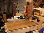
Here's mine so far...remember it's a work in progress and I'm not Ben Heck.
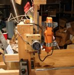
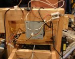
I quickly attached the electronics to show where they'd mount. Nothing's permanently attached so far. On the final build the wires will be cut to proper length, tied down, etc. This was just to show what was built. Please forgive the mess, it will look better on the final build. Also, kindly ignore the terrible mess in my garage, I'm sure it will look better once I die and someone cleans it (because it won't be me )
)
This is my own design, no plans, just an idea what I wanted and what I could do with material on hand (~$5 paid out for wood to build the frame). Once complete I'll probably use it to make a better version of itself. Until then I wanted to keep costs as low as possible.
Last motor test showed everything moved and performed as expected. What's left is to attach the table min and max sensors (just pushbuttons), and build a control console which will just be a bunch of switches for manual jog and resets and such. If I were smart I'd just buy a keypad I could read via SPI, but I have the switches already, so maybe for version 2.
In it's current form it can be controlled by a standard Arduino, once I add the switches I'll need to go to an Arduino Mega.
Control software is a g-code interpreter I found online. It's fed lines of g-code through the usb port. If I wanted, I could write a quick sketch to monitor step/dir pins for each axis and then connect it to the parallel port to give cad/cam software direct control. I will do this at some point to decide which way I like better. I can use my laptop with the g-code interpreter, but I've also got several old computers that could run linuxcnc easily.
I need to trim the Y Axis, it's 8-10 inches longer than it need to be. I also need another piece of 5/16-18 allthread since the one I used for Y and Z was old and rusted and just meant to act as a placeholder. I also have cooling fans for the motors and controllers, and an air hose to keep the cut path clear.
Cutter is a 1/2 hp trim router that will accept 1/8" or 1/4" shaft size bits so I could go as small as a 1/32" cutting bit. It only has a cutting depth of an inch (only 1/4" for the tiny cutter), but since this is meant to be a router/engraver, not a mill machine that should be fine.
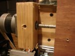
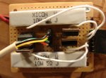
Steppers are from a surplus store and originally from a dot matrix printer. Controllers are home-made brute force style. Not very efficient but super cheap to build. Since this is for occasional home use not production, I'm fine with that. 3800 steps per inch and painfully slow (half an inch per minute for cutting, around 4 for jogging). I can probably speed this up without issue but that's where I'm starting.
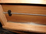
To couple to allthread to the steppers I cut a cross about an inch deep into the end of the rod, shoved it onto the shaft of the stepper, and used a bolt to tighten it. The stepper shaft is shaped as a cross and this worked better than set screws. It's not perfect though so I may try to machine a custom connector.
Bearings are heavy duty drawer slides, rated for 600 pounds. They're tighter and move freer than my original ball-bearing on a track attempts.
Cutting area is around 12"x16" with pieces up to 3" thick. Table space needed, around 30x36 inches plus whatever is needed for the computer. I have a tool cart it will fit perfectly upon.
Total price: around $65 so far, probably $10 more to spend...I'm not counting the arduino since it was previously owned and can be used for other projects, the PC power supply since it was, literally, taken from the trash, and most of the wood since it was also originally trash. To buy everything new, $150-$175 for everything except the steppers and probably $250 for those plus a professional controller.
When will it be done? No clue. I work on it in spurts, and it's cold in the garage right now. Future possibilities: RepRap extruder head to do 3d printing, and a laser head to scorch wood.
Misellus
Here's mine so far...remember it's a work in progress and I'm not Ben Heck.
I quickly attached the electronics to show where they'd mount. Nothing's permanently attached so far. On the final build the wires will be cut to proper length, tied down, etc. This was just to show what was built. Please forgive the mess, it will look better on the final build. Also, kindly ignore the terrible mess in my garage, I'm sure it will look better once I die and someone cleans it (because it won't be me
This is my own design, no plans, just an idea what I wanted and what I could do with material on hand (~$5 paid out for wood to build the frame). Once complete I'll probably use it to make a better version of itself. Until then I wanted to keep costs as low as possible.
Last motor test showed everything moved and performed as expected. What's left is to attach the table min and max sensors (just pushbuttons), and build a control console which will just be a bunch of switches for manual jog and resets and such. If I were smart I'd just buy a keypad I could read via SPI, but I have the switches already, so maybe for version 2.
In it's current form it can be controlled by a standard Arduino, once I add the switches I'll need to go to an Arduino Mega.
Control software is a g-code interpreter I found online. It's fed lines of g-code through the usb port. If I wanted, I could write a quick sketch to monitor step/dir pins for each axis and then connect it to the parallel port to give cad/cam software direct control. I will do this at some point to decide which way I like better. I can use my laptop with the g-code interpreter, but I've also got several old computers that could run linuxcnc easily.
I need to trim the Y Axis, it's 8-10 inches longer than it need to be. I also need another piece of 5/16-18 allthread since the one I used for Y and Z was old and rusted and just meant to act as a placeholder. I also have cooling fans for the motors and controllers, and an air hose to keep the cut path clear.
Cutter is a 1/2 hp trim router that will accept 1/8" or 1/4" shaft size bits so I could go as small as a 1/32" cutting bit. It only has a cutting depth of an inch (only 1/4" for the tiny cutter), but since this is meant to be a router/engraver, not a mill machine that should be fine.
Steppers are from a surplus store and originally from a dot matrix printer. Controllers are home-made brute force style. Not very efficient but super cheap to build. Since this is for occasional home use not production, I'm fine with that. 3800 steps per inch and painfully slow (half an inch per minute for cutting, around 4 for jogging). I can probably speed this up without issue but that's where I'm starting.
To couple to allthread to the steppers I cut a cross about an inch deep into the end of the rod, shoved it onto the shaft of the stepper, and used a bolt to tighten it. The stepper shaft is shaped as a cross and this worked better than set screws. It's not perfect though so I may try to machine a custom connector.
Bearings are heavy duty drawer slides, rated for 600 pounds. They're tighter and move freer than my original ball-bearing on a track attempts.
Cutting area is around 12"x16" with pieces up to 3" thick. Table space needed, around 30x36 inches plus whatever is needed for the computer. I have a tool cart it will fit perfectly upon.
Total price: around $65 so far, probably $10 more to spend...I'm not counting the arduino since it was previously owned and can be used for other projects, the PC power supply since it was, literally, taken from the trash, and most of the wood since it was also originally trash. To buy everything new, $150-$175 for everything except the steppers and probably $250 for those plus a professional controller.
When will it be done? No clue. I work on it in spurts, and it's cold in the garage right now. Future possibilities: RepRap extruder head to do 3d printing, and a laser head to scorch wood.
Misellus


