
Welcome to Laser Pointer Forums - discuss green laser pointers, blue laser pointers, and all types of lasers
How to Register on LPF | LPF Donations

Navigation
Install the app
How to install the app on iOS
Follow along with the video below to see how to install our site as a web app on your home screen.
Note: This feature may not be available in some browsers.
More options
You are using an out of date browser. It may not display this or other websites correctly.
You should upgrade or use an alternative browser.
You should upgrade or use an alternative browser.
DIY Homemade laser diode driver
- Thread starter Daedal
- Start date
- Status
- Not open for further replies.


rog8811
0
- Joined
- Jul 24, 2007
- Messages
- 2,749
- Points
- 0
No idea, use the search function, just remember to change the search period to a year.
Regards rog8811
Regards rog8811
Hello, just a quick question, i'm trying to build a driver for StoneTek IR diode, but i don't understand few things.
I'm using 4,3ohm resistor and 100ohm pot. If i want 250mA, the resistance setting for the pot should be (1,25/0,25)-4,3=0,7ohm ? That seems to be very hard to get on 100ohm range.
Also, could i damage LM317 if i connect resistors on the ADJ pin instead of OUT one?
Thanks in advance")
EDIT: and one more question, the pot is actually trimmer with 25 turns over full range, but could i break it if i turned too much or too often?
I'm using 4,3ohm resistor and 100ohm pot. If i want 250mA, the resistance setting for the pot should be (1,25/0,25)-4,3=0,7ohm ? That seems to be very hard to get on 100ohm range.
Also, could i damage LM317 if i connect resistors on the ADJ pin instead of OUT one?
Thanks in advance
EDIT: and one more question, the pot is actually trimmer with 25 turns over full range, but could i break it if i turned too much or too often?
rog8811
0
- Joined
- Jul 24, 2007
- Messages
- 2,749
- Points
- 0
It should hit 250ma as you get to zero on the pot, the pot has a clutch in it you will hear it click when you turn it when it is on the end stop.I'm using 4,3ohm resistor and 100ohm pot. If i want 250mA, the resistance setting for the pot should be (1,25/0,25)-4,3=0,7ohm ? That seems to be very hard to get on 100ohm range.
You will have connected the resistor between the ADJ and OUT anyway but you need the LD connected to ADJ pin to get the reg to work.Also, could i damage LM317 if i connect resistors on the ADJ pin instead of OUT one?
Regards rog8811
rog8811 said:It should hit 250ma as you get to zero on the pot, the pot has a clutch in it you will hear it click when you turn it when it is on the end stop.I'm using 4,3ohm resistor and 100ohm pot. If i want 250mA, the resistance setting for the pot should be (1,25/0,25)-4,3=0,7ohm ? That seems to be very hard to get on 100ohm range.
You will have connected the resistor between the ADJ and OUT anyway but you need the LD connected to ADJ pin to get the reg to work.Also, could i damage LM317 if i connect resistors on the ADJ pin instead of OUT one?
Regards rog8811
Thaks! got it working. This is really helpful thread, I'm now a proud father of IR laser x)
rog8811
0
- Joined
- Jul 24, 2007
- Messages
- 2,749
- Points
- 0
well done on to the next build then....you know you want to...
Regards rog8811
on to the next build then....you know you want to...Regards rog8811
Asherz
0
- Joined
- Jan 18, 2009
- Messages
- 1,623
- Points
- 0
hey,
I am currently buying the parts I need to follow out this tutorial,
and as I'm in the UK I'm buying things from maplins, and so far I purchased a 4.7 ohm resistor, 35V 47UF capicitor, a LM317T
and with the pot I wasn't really sure because I couldn't find one that looks like the one in any guides, but it says it's 100ohms and you can turn the thing on top, but it's circular with two silver pins on one side and 1 on the other side:
heres a link to it on maplins, I purchased the very top one which is 100ohm: http://www.maplin.co.uk/Module.aspx?ModuleNo=6499
thanks, just wandering if you could tell me if there all ok, as for the 1N4001 diode I've orderd it in as they did have any stock.
Is this also possible to put together on a little circuit board? I might have a shot at that.
rog8811
0
- Joined
- Jul 24, 2007
- Messages
- 2,749
- Points
- 0
Asherz
0
- Joined
- Jan 18, 2009
- Messages
- 1,623
- Points
- 0
Much love!  (not in a gay way
  )
)
Thanks very much, Will be carefull when adjusting, just a few quickys,
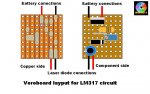
what is the grey wire above the pot and below the resistor?
When you first put the diode through the driver, do your turn the pot all the way to the left/right (not sure) then adjust it until it lights and stop or?
Also how do you discharge the capicitor if you run electricity through it before putting the diode in?
thanks again
-Ash
(not in a gay way )Thanks very much, Will be carefull when adjusting, just a few quickys,
what is the grey wire above the pot and below the resistor?
When you first put the diode through the driver, do your turn the pot all the way to the left/right (not sure) then adjust it until it lights and stop or?
Also how do you discharge the capicitor if you run electricity through it before putting the diode in?
thanks again
-Ash
rog8811
0
- Joined
- Jul 24, 2007
- Messages
- 2,749
- Points
- 0
I typed a long answer to this, when I tried to post it the site was being backed up 
what is the grey wire above the pot and below the resistor?
It is just a wire link between 2 tracks
When you first put the diode through the driver, do your turn the pot all the way to the left/right (not sure) then adjust it until it lights and stop or?
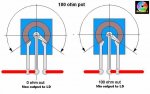
you will need a bit more room on the board for your pot but you will need to connect one of the 2 pins to the middle top one. drawing shows which way you will turn the pot depending on which way you connect it....if you see what I mean :-/
Also how do you discharge the capicitor if you run electricity through it before putting the diode in?
connect the red and black output wires together with a screwdriver or some other metal item
Regards rog8811
what is the grey wire above the pot and below the resistor?
It is just a wire link between 2 tracks
When you first put the diode through the driver, do your turn the pot all the way to the left/right (not sure) then adjust it until it lights and stop or?
you will need a bit more room on the board for your pot but you will need to connect one of the 2 pins to the middle top one. drawing shows which way you will turn the pot depending on which way you connect it....if you see what I mean :-/
Also how do you discharge the capicitor if you run electricity through it before putting the diode in?
connect the red and black output wires together with a screwdriver or some other metal item
Regards rog8811
Attachments
Asherz
0
- Joined
- Jan 18, 2009
- Messages
- 1,623
- Points
- 0
thanks mate, apreciated ")
Hi All.
Question: I have read on multiple sites and threads that it is best to solder to the LD to the Capacitor, because if the capacitor disconnects and reconnects to the LD whilst it powered, it will kill the LD, by discharging everything its got through it. What I cant understand is, how are you suppose to switch the circuit on and off? Once you switch the circuit off, do you short out the capacitor manually and then start again or can you leave the capacitor as it is? At the minute I think that you can leave it as it is, because it will discharge once you have switched off the circuit and be ready to take any voltage spikes on the next start-up. Is this how the Dr.Lava and flexdrive drivers work?
I checked out your site Rog8811, very informative! On your site you have a 10mF,16V cap but at the start of this thread there is a 16uF,35V cap. From looking at the numbers, it seems like they are both going to do the same job but what’s the advantage of using a lower voltage and higher capacity to store charge?
Kind Regards,
--XsR
rog8811
0
- Joined
- Jul 24, 2007
- Messages
- 2,749
- Points
- 0
With the cap directly on the LD you do not have to do anything to discharge it, as long as it is a permanent fixture it will not do any harm to the LD.
You are right in thinking that the mfd of the cap is relatively unimportant, the voltage rating is the important bit, it should be around 3 times the LD voltage or above to ensure it catches any spikes.
The 10mfd one is a convenient size to fit in the module, you can always use tantalum caps as they are even smaller.
Regards rog8811
Cheers for the reply.
What I cant get my head over is say if I use a 35V cap, I switch on the current, LD fires, switch off the current... at this point does the Cap discharge itself into the LD? and it will be empty for the next time the laser will be switched on?
What’s also confusing me is the diode in the circuit. Are the diagrams shown on the first page of this thread showing conventional or electron flow? If it is showing conventional flow then (positive to negative) then the diode acts as a gate and just blocks the current to the positive side of the capacitor and the LD?
Rog8811 on your site you show how to measure the dummy loads (../laserdriver.htm). Do you think it would be possible to work out the power of the LD using the same method (the 4xIN4001 are replaced with the LD and the 1R is added to the circuit): Measure the mV across the 1ohm to get the current to the LD (I=V/R=mv/1 [mA]), Measure the V across the LD. To calc Power, P=VI. The Voltage in a series series circuit drops but the current throughout stays the same, and by measuring the voltage across the LD and the current going to the LD, and this would infact give the theoretical power from the LD? The two readings would have to be taken instantaneously. The true power of the LD can only be measured from the beam using a laser power meter.
Any help would be greatly appreciated.
rog8811
0
- Joined
- Jul 24, 2007
- Messages
- 2,749
- Points
- 0
Cheers for the reply.
What I cant get my head over is say if I use a 35V cap, I switch on the current, LD fires, switch off the current... at this point does the Cap discharge itself into the LD? and it will be empty for the next time the laser will be switched on?
I am not 100% sure how this works, I have always assumed that the cap gradually releases any overcharge over time, if you have room you could always put a resistor across the capacitor which will discharge it.
What’s also confusing me is the diode in the circuit. Are the diagrams shown on the first page of this thread showing conventional or electron flow? If it is showing conventional flow then (positive to negative) then the diode acts as a gate and just blocks the current to the positive side of the capacitor and the LD?
The diode in the circuit is reverse polarity, it is only there to protect the LD should the power supply be applied the wrong way round (electron flow goes though diode rather than trying to go through the LD.
Rog8811 on your site you show how to measure the dummy loads (../laserdriver.htm). Do you think it would be possible to work out the power of the LD using the same method (the 4xIN4001 are replaced with the LD and the 1R is added to the circuit): Measure the mV across the 1ohm to get the current to the LD (I=V/R=mv/1 [mA]), Measure the V across the LD. To calc Power, P=VI. The Voltage in a series series circuit drops but the current throughout stays the same, and by measuring the voltage across the LD and the current going to the LD, and this would infact give the theoretical power from the LD? The two readings would have to be taken instantaneously. The true power of the LD can only be measured from the beam using a laser power meter.
I have never tried what you suggest but the logic behind it seems right. IR laser diodes are usually 1.5 to 2.0v so 2 or 3 1N1004 diodes should be the correct load for initial setup.
Any help would be greatly appreciated.
We aim to please
Regards rog8811
Thank you Rog8811.
Just a brainwave on the Capacitor. The electrons will flow from the LM317T to the Diode junction. Here they will be blocked here (if you look at it as conventional flow). Next is the capacitor junction, here the electrons charge up the capacitor, more importantly any large Charge from the batteries is buffered here. Next is the LD. On switch off, the electrons from the capacitor will pass through the LD to the neautalise itself. And the time taken for it to charge up and down is related to the time constant of the circuit. I think this has been sussed out now!
On the construction of this, it is advised to solder the capacitor directly onto the LD. If I do that and then test it by using crocodile clips to connect it to the driver, there shouldnt be any problem with that?
Kind Regards, --XsR
- Status
- Not open for further replies.