
Welcome to Laser Pointer Forums - discuss green laser pointers, blue laser pointers, and all types of lasers
How to Register on LPF | LPF Donations

Navigation
Install the app
How to install the app on iOS
Follow along with the video below to see how to install our site as a web app on your home screen.
Note: This feature may not be available in some browsers.
More options
You are using an out of date browser. It may not display this or other websites correctly.
You should upgrade or use an alternative browser.
You should upgrade or use an alternative browser.
DIY Homemade laser diode driver
- Thread starter Daedal
- Start date
- Status
- Not open for further replies.


H
High_Octane
Guest
Daedal said:
Congrats... pictures? Ideas? :
--DDL
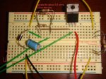
Here are a few pics.


As far as ideas, Yes I am currently working on a LED power meter.
I have to find the chip that controlls the LED BAR, It will light each bar as the voltage increases.
Its in my garage somewhere :
") I built an O2 meter with it, to adjust and monitor fuel mixtures. All from Rat Shack. I'll post the Chips number as soon as I find it.
I built an O2 meter with it, to adjust and monitor fuel mixtures. All from Rat Shack. I'll post the Chips number as soon as I find it.I think the Power Meter would be cool for a visual aid to keep from hooking a meter up constantly, and maybe help to prevent from frying LDs.
H
High_Octane
Guest
Well I found that O2 Meter in my tool box in the garage.
Here are a few pics of it and its circuit. Guess I have another container for a box style laser


Here is what the chip has printed on it JB112AF & [highlight]LM3914N-1[/highlight]
Heres a link to the Data Sheet http://pdf1.alldatasheet.com/datasheet-pdf/view/8900/NSC/LM3914N-1.html
And where to get it http://www.digikey.com/scripts/DkSearch/dksus.dll?Detail?name=LM3914N-1-ND
For the LED BAR, The Part# [highlight]1001HDA[/highlight]
And where to get it http://www.digikey.com/scripts/DkSearch/dksus.dll?Detail?name=LM3914N-1-ND
The LED Part# above is for a LED with 10 RED bars, I have another one that is similar, However it has 7 green and 3 red bars. I like it much better. A similar one with 6 green and 4 red can be purchased Here http://www.gatewayelex.com/led.htm

I'm sure with the proper resister, this circuit could be modified to work the the voltages that DDLs driver uses.
10 Segment red LED bar graph display- 20-pin DIP 20mA, 2VDC per element.
I'll post more information as I progress.
Here are a few pics of it and its circuit. Guess I have another container for a box style laser
Here is what the chip has printed on it JB112AF & [highlight]LM3914N-1[/highlight]
Heres a link to the Data Sheet http://pdf1.alldatasheet.com/datasheet-pdf/view/8900/NSC/LM3914N-1.html
And where to get it http://www.digikey.com/scripts/DkSearch/dksus.dll?Detail?name=LM3914N-1-ND
For the LED BAR, The Part# [highlight]1001HDA[/highlight]
And where to get it http://www.digikey.com/scripts/DkSearch/dksus.dll?Detail?name=LM3914N-1-ND
The LED Part# above is for a LED with 10 RED bars, I have another one that is similar, However it has 7 green and 3 red bars. I like it much better. A similar one with 6 green and 4 red can be purchased Here http://www.gatewayelex.com/led.htm

I'm sure with the proper resister, this circuit could be modified to work the the voltages that DDLs driver uses.
10 Segment red LED bar graph display- 20-pin DIP 20mA, 2VDC per element.
I'll post more information as I progress.
H
High_Octane
Guest
I ran across this and was thinking it could possibly be used to TEST LDs.
Is this feasible? Of course you would have to clip the 3 pin on the LD in order to fit it into the socket.
http://www.alltronics.com/cgi-bin/item/27Z001/31/Pocket-size-LED-Tester

Is this feasible? Of course you would have to clip the 3 pin on the LD in order to fit it into the socket.
Pocket size LED - Tester
You can carry this light (no pun intended) pocket sized tester around with you and test LED’s all day long. The socket strip provides 2mA, 10mA, 20mA, 30mA, and 50mA drive currents. There are 7 of the 10mA sockets so you can do side by side comparisons of the color and brightness for up to 7 LED’s. This useful tester requires a 9-Volt battery (not included) and has a push-to-test button that is also used to drive the green battery-check LED. Approximate size is 2 3/8” W by 3” H by 7/8” D.
http://www.alltronics.com/cgi-bin/item/27Z001/31/Pocket-size-LED-Tester
What a coincidence, I just got a LM3914 last week for my LD circuit It works great! I still have to put it in my torch, i only tested it with some leds, not a bar display. I wanted to measure the current through the LD, so i set it up to about 25mA per segment 0-250mA.
It works great! I still have to put it in my torch, i only tested it with some leds, not a bar display. I wanted to measure the current through the LD, so i set it up to about 25mA per segment 0-250mA.
H
High_Octane
Guest
naplam said:What a coincidence, I just got a LM3914 last week for my LD circuit
Glad to hear it! Please keep me/us updated, I would like to see how you set it up.
I opened a new thread about it.High Octane said:Glad to hear it! Please keep me/us updated, I would like to see how you set it up.
When I finished assembling my driver i tested the voltage it was putting of and it was still 5.8. i am using 4 aa batteries to power it at 6v. Do you know what the problem could be i think i have everything connected right. I am trying to get everything straightened out before my LD gets here. Sorry if i sound stupid i am fairly new at this.
The first thing I'd check is that the pin numbers on the LM317 are what you think they are. If you used a TO-220 case part like you'd find at Radio Shack, the pins are Vin, Vout, Adj, as read from RIGHT to LEFT. That's different than from in the schematic at the top of this thread.
Gazoo
0
- Joined
- Jun 9, 2007
- Messages
- 3,206
- Points
- 38
Hello stump and welcome to the forum.
You need a load across the output to test your circuit. Please read through the following thread for your answers..")
http://www.laserpointerforums.com/forums/YaBB.pl?num=1191361180
You need a load across the output to test your circuit. Please read through the following thread for your answers..
http://www.laserpointerforums.com/forums/YaBB.pl?num=1191361180

- Status
- Not open for further replies.