Welcome to Laser Pointer Forums - discuss green laser pointers, blue laser pointers, and all types of lasers

LPF Donation via Stripe | LPF Donation - Other Methods

Links below open in new window

ArcticMyst Security by Avery

Dead M140?

IVO

0
Joined
Jun 2, 2017
Messages
15
Points
0
Hello there!

My name is Ivo, and this will be my first laser.
I'm an electronics hobbyist, so I'm not new to electronics but my knowledge about lasers is only theoretical...
I've been reading, planning and designing for a long time. But now I have some parts and I was ready to make my first laser... but I think it died.

So first I tested the aixiz copper modules with a DVD red laser diode, because I wanted to try pressing this diode first so I don't screw it up with the M140-M. Something like training... The results were very nice at 170mA (very safe current), so I went up to 270mA with no problem and almost no heat.

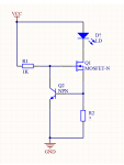
I'm using a homemade constant current driver based on a N channel MOSFET and a NPN transistor.

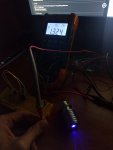
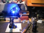
But when I decided to go for the M140... I noticed something was wrong. At 270mA with the same driver the beam was weak. But when I increased the current to 330mA, the same brightness. At 600mA, the same... and at 1.3A the same weak beam, but everytime with more heat. The voltage drop of the diode is 4.96V (isn't that a little bit high?). See pictures:
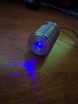
Laser.jpg
laser2.jpg

Oh, by the way... the small driver wasn't powerful enough so I built the circuit on a protoboard an I used a 12V LED PSU as power.

Mi guess is that the diode is died because of ESD or a peak... But I really hope I'm wrong...
Anyway... At least he red one is nice. XD

Thank you!


Joined
Sep 20, 2013
Messages
17,388
Points
113
If you used an LED driver for this laser diode, that is probably the problem. LED drivers are noisy, and though that is not a problem for LEDs, it is for LDs. The typical current used to run an M140 diode is 1.8 amps. Sounds like the laser diode LEDed. That is when the emitter facet is damaged and it won't lase but continues to draw power and expend some of it as heat.
 
Joined
Dec 15, 2014
Messages
6,782
Points
113
Hi AVO,
pauliscorrect the drivers for a led are not good for a m40, You need a bucking driver like the ones DTR sell set to 1.8A . You will get between 1.8 and over 2W's depending on the efficiency of the diode.her is one that is set to 1.8A and it delivers 1900+ . most of the laser s i build are over 2W's +

Rich:)

Hi Paul,
How do you like the 500 Mitsu ??

Rich:)
 

Attachments

  • IMG_2983.JPG
    IMG_2983.JPG
    219.7 KB · Views: 45
Last edited:

IVO

0
Joined
Jun 2, 2017
Messages
15
Points
0
Thanks for the fast response.

The driver is not a LED driver. I made it to use it with high power LEDs, but it's a general purpose linear constant current circuit. It's not a switch mode driver, so the only noise could have come prom the PSU. One thing I didn't include were capacitors to filter the input and output... Maybe that's the problem?

driver.png

Well there's nothing I can do about the laser. By the way... tat's not the driver that I'll be using in the final laser. I'm designing a switch mode boost driver. But I really would like to know what exactly killed it in this case... That way the lesson will be worth it.

And, I don't like buying circuits... I know that they are probably very good, but where's the fun? hahaha I prefer to make them. That way I learn so much more...

Thanks again!
 
Last edited:

Benm

0
Joined
Aug 16, 2007
Messages
7,896
Points
113
Well, your driver is a textbook example of a simple linear constant current driver, and if built correctly is not the cause of the problem here.

I use similar drivers as a first thing when there is enough margin between supply voltage and diode voltage, using a power transistor or mosfet for the output power driver. Those things are solid, if you set them to 500 mA they'll drive 500 mA into any load as long as the voltage is sufficient, regardless if it is a laser diode, capacitor, inductor, or piece of plumbing pipe.

I'm affraid your diode is dead, led'ed. A normal M140 should be lasing at 270 or 330 mA, with a pretty visible beam if you have a lens installed and don't live in a brightly lit cleanroom.
 
Joined
Sep 20, 2013
Messages
17,388
Points
113
What Benm said is true, but you haven't given enough information in your schematic of your linear driver to know what current it would set to, or if your supply had enough headroom to supply the driver with the voltage it needed to meet the LD's requirements. Also, if there was enough current available to supply what your set point was. There are too many unanswered questions to even speculate at this point as to why it LEDed. But, from what you said in the OP, I can tell you that the LD is now an LED.

Hi, Rich. I love the Mits ML501P73 build and plan to do a review of it when I finally get everything else that came before off my plate. Sorry it isn't already done and posted.
 
Joined
Jun 20, 2015
Messages
244
Points
43
You could also try using a LM350 on a heatsink with a pair of 1.5 ohm resistors in parallel to yield .75 ohm for the set current. This should give you about 1.7 amps for the drive current.. you will need at least 2 watt resistors but would be better off with 5 watt units. It's certainly possible that the diode failure had nothing to do with your power supply at all, you seem to know what you're doing with circuit design even though you're new to lasers but thought I'd offer my experience on a power source that I've used many times and has never failed me.. also be sure to ground yourself out by touching something like bare metal on a grounded computer case or use a ground strap before handling diodes.
 

diachi

0
Joined
Feb 22, 2008
Messages
9,700
Points
113
You could also try using a LM350 on a heatsink with a pair of 1.5 ohm resistors in parallel to yield .75 ohm for the set current. This should give you about 1.7 amps for the drive current.. you will need at least 2 watt resistors but would be better off with 5 watt units. It's certainly possible that the diode failure had nothing to do with your power supply at all, you seem to know what you're doing with circuit design even though you're new to lasers but thought I'd offer my experience on a power source that I've used many times and has never failed me.. also be sure to ground yourself out by touching something like bare metal on a grounded computer case or use a ground strap before handling diodes.

If you can't find an LM350 then an LM338 will do the job too, and then some. Going to need a heatsink for the regulator at those sorts of currents.

Anti-static strap is a good idea, laser diodes are very sensitive to ESD. I make a point of using a strap here as the air is usually very dry so static shocks happen frequently.

Could just be bad luck here unfortunately.

One thing to make sure you don't do is power your driver without the diode connected and then connect the diode. Seeing as it's a constant current driver it'll ramp up to maximum possible output voltage when there is no load attached. Any capacitors on the output will be sitting at that voltage when you attach your diode, killing it.
 
Joined
Sep 20, 2013
Messages
17,388
Points
113
This is why I don't like to use linear drivers for higher power laser diodes. Lots of waste heat. I think they are great for low power diodes. Also, If you are planning on making this into a pointer, there just isn't room for the heat sink, 5 watt resistors, etc. My work bench has a grounded mat, and I have a grounded wrist strap for myself, even though it is raining here most of the time and ESD isn't something one needs to worry about much. It is much better to be over protected than lose an expensive diode to an ESD you can't even feel.
 
Last edited:
Joined
Jun 20, 2015
Messages
244
Points
43
This is why I don't like to use linear drivers for higher power laser diodes. Lots of waste heat. I think they are great for low power diodes. Also, If you are planning on making this into a pointer, there just isn't room for the heat sink, 5 watt resistors, etc.

Totally agree.. I usually make lab style lasers so I wasn't even thinking about space constraints.. so yeah.. what he said :)
 

diachi

0
Joined
Feb 22, 2008
Messages
9,700
Points
113
This is why I don't like to use linear drivers for higher power laser diodes. Lots of waste heat. I think they are great for low power diodes. Also, If you are planning on making this into a pointer, there just isn't room for the heat sink, 5 watt resistors, etc.

Yeah, linear is fine if you can deal with the waste heat and inefficiencies, they're simpler, less noisy etc. Just not always practical, lots of heat, often heavy/bulky. Although they are a must for some applications.

Buck is the way to go if you can find one that's suitable or you're capable of building one that's reliable.
 

IVO

0
Joined
Jun 2, 2017
Messages
15
Points
0
Thanks all for the replies.


Let's go by parts, as Jack the ripper said...


For my first test I connected the diode to the driver that I used to test the red DVD laser. To set the current I used two 1.8R in series and one 5.6R in parallel to make a total of 2.2R. The threshold of the diode is 0.55V, ad as we know V=I*R. So it should give me 250mA, but due to the tolerances, 270mA is within the margin of error. For the power I used a modified power bank that has a 18650 inside and provides 5V. This worked for the DVD diode, but due to the voltage drop across the mosfet, the resistors in series and the high forward voltage of the M40-M (about 4.8V) it was not enough. So I tried with a 9V to give enough headroom. And I think it was working:

Laser3.jpg


But then, I needed to test with higher current, so I built the circuit on a proto board, set it to 600mA and powered it with a 12V LED strip PSU. And I think it was here when I messed up the diode:

One thing to make sure you don't do is power your driver without the diode connected and then connect the diode. Seeing as it's a constant current driver it'll ramp up to maximum possible output voltage when there is no load attached. Any capacitors on the output will be sitting at that voltage when you attach your diode, killing it.

Yeah... I did that. Before I connected the diode I turned on the supply and measured the current connecting a LED as a load, just to make sure it was OK. And then I connected the diode. But I didn't have any capacitors connected. Maybe the small amount of time the voltage was high before stabilizing was enough to kill the diode... But I don't think it died then, because the beam was brighter and it warmed my finger, so my guess is that it was working then.

But now I remember that I adjusted the current with the diode still on. I placed another resistor in parallel, raising the current up to 900mA. And the beam seemed weak in my opinion, but I haven't seen how does a M140 at 900mA look like, so I wasn't sure. It was when I raised the current up to 1.2A when I realized that it might be dead because the beam was too weak.


So is that it? Adjusting the current while the diode is still working? The jump from 600mA to 900mA? But 900mA is a reasonable current for this diode, maybe the fast change was enough to kill it?


Or maybe was ESD? I know that they're sensitive, but what are the chances? I didn't use a wrist strap, but it was in an antistatic bag until I pressed it into the module and I usually ground myself touching the case of my PC.


You could also try using a LM350 on a heatsink with a pair of 1.5 ohm resistors in parallel to yield .75 ohm for the set current. This should give you about 1.7 amps for the drive current.. you will need at least 2 watt resistors but would be better off with 5 watt units. It's certainly possible that the diode failure had nothing to do with your power supply at all, you seem to know what you're doing with circuit design even though you're new to lasers but thought I'd offer my experience on a power source that I've used many times and has never failed me.. also be sure to ground yourself out by touching something like bare metal on a grounded computer case or use a ground strap before handling diodes.

Thanks for the advise. I've tried the lm317 circuit before for smaller currents, and I know it works but I don't have 5W resistors at the moment, but when I get some I'll try it.


Another dead solider, I'll light a

Hahaha I appreciate that, but I think the lesson is more valuable that the laser... I'll have to save up some money, but it's not so bad, just a bad feeling. I've been waiting this moment for so long and it dies, just like that...


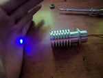
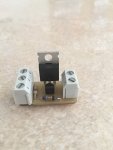
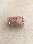
I understand the advantages and disadvantages of linear power supplies. I used that just for the tests. In the real world they're too big and inefficient to put in a final project. For the final laser I'm designing a small boost current regulator. I'm still looking for a good IC. When I finish it I'll make a post about it. This is the linear driver. I made it a long ago.
IMG_2606.JPGIMG_2607.JPG
 
Last edited:
Joined
Jun 20, 2015
Messages
244
Points
43
Before I connected the diode I turned on the supply and measured the current connecting a LED as a load, just to make sure it was OK. And then I connected the diode. But I didn't have any capacitors connected. Maybe the small amount of time the voltage was high before stabilizing was enough to kill the diode...

This was probably it, even though it didn't show damage at the time it's often that it's enough that after shutting down it shows itself the next time power is applied.

So is that it? Adjusting the current while the diode is still working? The jump from 600mA to 900mA? But 900mA is a reasonable current for this diode, maybe the fast change was enough to kill it?

I'm inclined to say it's doubtful.. I'm not sure about your circuit but I do know that on LM317 designs that current can be adjusted with the power on in the way you describe.
 

Benm

0
Joined
Aug 16, 2007
Messages
7,896
Points
113
Lets clear something up real quickly here: Linear drivers are not the problem. Using voltage regulators as linear drivers mostly is.

The problem with voltage regulators like the LM317 or LM350 is that they:

- need a substantial voltage difference between input and output pin to work reliable, per the datasheet 3 volts though you can get away with less in some cases.

- are 'abused' in the sense that you use the reference voltage of 1.25 volts over a shunt resistor to get constant current.

These two things combined mean you need a 4.25 volt total voltage drop for reliable operation. I think DDL mostly pioneered this approach back in the day where 200 mW-ish red diodes were 'the thing' and power source was usually 2 lithium ion batteries in series, which makes a decent match for the whole setup. Parts were cheap, it was easy to build, and even had short-circuit and overheat protection built in the LM317. For that era it was a great solution.

But now fast-forward a decade: We're looking at 445 nm laser diodes that run at about 6 volts, currents of an amp or more, powered by 7.4 to 8.4 voltsof input power from lithium cells.

With these battery and diode voltages linear drivers are still quite feasibly, but NOT something re-using a voltage regulator chip from the 70s. You -can- build linear drivers with a dropout of less than a volt using opamps, mosfet drivers and low value sense resistors, and they work perfectly well.

With the laser running at 6.0 volts and the batteries providing 7.4 the efficiency is not that bad either at about 80%. Switchmode regulators can do a tad better, but add a lot of complexity to the point where you cannot build them from scratch at home.
 
Joined
Jun 20, 2015
Messages
244
Points
43
Lets clear something up real quickly here: Linear drivers are not the problem. Using voltage regulators as linear drivers mostly is.

The problem with voltage regulators like the LM317 or LM350 is that they:

- need a substantial voltage difference between input and output pin to work reliable, per the datasheet 3 volts though you can get away with less in some cases.

- are 'abused' in the sense that you use the reference voltage of 1.25 volts over a shunt resistor to get constant current.

These two things combined mean you need a 4.25 volt total voltage drop for reliable operation. I think DDL mostly pioneered this approach back in the day where 200 mW-ish red diodes were 'the thing' and power source was usually 2 lithium ion batteries in series, which makes a decent match for the whole setup. Parts were cheap, it was easy to build, and even had short-circuit and overheat protection built in the LM317. For that era it was a great solution.

But now fast-forward a decade: We're looking at 445 nm laser diodes that run at about 6 volts, currents of an amp or more, powered by 7.4 to 8.4 voltsof input power from lithium cells.

With these battery and diode voltages linear drivers are still quite feasibly, but NOT something re-using a voltage regulator chip from the 70s. You -can- build linear drivers with a dropout of less than a volt using opamps, mosfet drivers and low value sense resistors, and they work perfectly well.

With the laser running at 6.0 volts and the batteries providing 7.4 the efficiency is not that bad either at about 80%. Switchmode regulators can do a tad better, but add a lot of complexity to the point where you cannot build them from scratch at home.


I'm not sure what you're saying.. if you're saying that using a linear driver is impractical for handheld builds, we've already established that. If you're saying that using an lm317 or lm350 in current control operation is unreliable, unsafe or has inferior output.. I would have to disagree.

Edit- Nevermind, I re-read what you wrote and I'm pretty sure you're just talking about the dropout voltage not having enough "play" using a lion power source... sorry for the misunderstanding.
 
Last edited:


Top