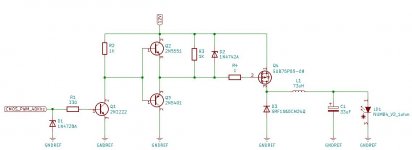
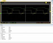
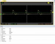
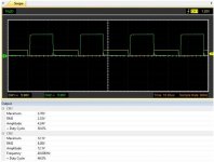
That's the point, an step down circuit can establish a limit voltage (without taking in consideration the losses in the circuit), a laser diode is that, A DIODE, and diodes works depending the voltage that is provide for the source, in the case of the graphic you are providen 5V to the diode, the current will be demanded depending the laser diode model. But if you set your dutty cycle, at 10% there's a diferent voltage provided,
View attachment 70758
You'll supplied 1.51V at D=10%, the diode will not consume more current than that, I mean, it's impossible supply more voltage 'cause the inductor and the capacitor settles this, and with an acceptable peak on the first milisecond, you can control perfectly you circuit.
This is important, I'M NOT SAYING THAT A PID CONTROLLER ON DISCONTINUOS CONDUCTION MODE IT'S NOT NECESSARY, acutally PID it's better for mechanis, for electronics a P loop it's better this is a BASIC SOLUTION, compare this with an LM311, that you're turning on and off the diode, YOU'RE KILLING THE DIODE, this step down gives you a CONTINUOUS SIGNAL.
Just to clarify you about the application of loop controllers, it's a design criteria that a signal for a DC-DC converter should be higher than 20KHz (DW Hart, Power Electronics, 2011), if you're considerating a variation higher than 0.01V (than means less than 5% of the signal), you must use PID controller on accurate, 'cause an peak of at leats 2 times your inital voltage is created, that why you need a PID in that application that can be for example in PCB's solding created with lasers.
I'M SHOWING A BETTER ALTERNATIVE, most of the time people just buy a driver laser, instead of created one, this is a good point start.


