Welcome to Laser Pointer Forums - discuss green laser pointers, blue laser pointers, and all types of lasers

Buy Site Supporter Role (remove some ads) | LPF Donations

Links below open in new window

FrozenGate by Avery

Circuits !

  • Thread starter Thread starter SenKat
  • Start date Start date
S

SenKat

Guest
Let's discuss some circuits in this thread - we have circuit discussions in almost EVERY thread out there at present, and it is getting difficult to find all the relevant posts :-) I just figured maybe we can start new threads with the relevant info, and then pop them up as stickies for future use ! It iwll cut down on redundant questions, and make the info a LOT easier to find :-)

So - even though threads may already exist with the info in them - the author/inventor of each circuit - whether they be store bought (roitner, etc) or Daedal's now famous circuits, or the equally impressive, and none the less famous scanner parts lists, and circuits - let's get them organized so we can ALL benefit from one central depository of the info :-)

G !


Re: Circuits ! Sam Goldwasser's dual 317 supply

I'll add Sam Goldwasser's voltage and current power supply. Both voltage and current are independently adjustable using a pair of LM317's:

http://www.repairfaq.org/sam/laserdps.htm#dpssglt1

In addition, not shown in the schematic, Sam highly recommends adding the following components directly across the laser diode: a parallel combination of a 1K ohm resistor, 0.1 uF capacitor, and reverse polarity fast diode permanently across the laser diode.
 
Re: Circuits ! circuit for non-reg lasers

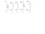
Laser Diode Protection when using just a dropping resistor (no regulation). See photo for schematic.

1 Laser Diode
2 0.1 uF low ESR ceramic SMT RS 424-8104 Allied Electronics
3 22 uF 10 V tantalum SMT RS 406-9918 Allied Electronics
4 MURS120 Ultrafast Diode RS 469-0865
5 Memory capacitor or“double layer” cap 0.33F- 1.0 F

** NEVER connect laser diode without discharging circuit first!!**
** Surface mount components are highly recommended.**
**Circuit was suggested in response to usenet inquiries**
 

Attachments

  • simple.JPG
    simple.JPG
    9.9 KB · Views: 184
Excellent input thus far ! As well as schematics - can you all see if it is possible to post a drawing of the circuit ? What I would like to see for some folks that may be uncomfy with schematics is similiar to this :
 

Attachments

  • sample.jpg
    sample.jpg
    24.3 KB · Views: 234
just for you all who want an easy way to make small circuits, i use microsoft word, and little thumbnails of the components. here is an example.
if anyone wants the symbols, just ask and i'll send them ;)
 

Attachments

  • Marx_Generator.PNG
    Marx_Generator.PNG
    18.5 KB · Views: 2,772
things said:
well to start off, i am currently asking daedal if this circuit will work. http://jaycar.com.au/productView.as...d2=&pageNumber=&priceMin=&priceMax=&SUBCATID=
it uses the LM317T like daedals, but it has a circuit board, and minimal component count. read the description on that link for full info!. i have contacted daedal to see if it will control the GB diodes, because it is a voltage regulator.

Sorry things but I will bet you Daedal will give you basically the same explanation I did. Who do you think spent the most time convincing me a voltage regulator is not a good idea for powering laser diodes.. ;)
 
thats fine gazoo, he said there was a very simple mod i have to do to make it regulate current. i can even still use the same PCB, and cut it down abit.
 
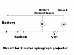
Basic 2 motor spirograph circuit. With the correct variable resistor (VR1) you will be able to stop one of the motors and produce a great number of spiro patterns.

To find the value of VR1 connect the motor to a battery with a multiturn trim pot (5k..ish) Turn resistance right off (motor full speed) wind in the resistance until the motor stops. Disconnect everything and measure the resistance of VR1 with a meter. You will now know the best value for VR1 to get the finest control of motor speed.

Regards rog8811
 

Attachments

  • Circuit01_001.jpg
    Circuit01_001.jpg
    66.6 KB · Views: 256
things said:
just for you all who want an easy way to make small circuits, i use microsoft word, and little thumbnails of the components. here is an example.
if anyone wants the symbols, just ask and i'll send them ;)

I'd like to have them please ;D I'll send a PM with my e-mail address :)
 
ok i think this might be good for a sticky, but i found how to attach the symbols!
 

Attachments

SenKat said:
Excellent input thus far !  As well as schematics - can you all see if it is possible to post a drawing of the circuit ?  What I would like to see for some folks that may be uncomfy with schematics is similiar to this :


Umm.....I think in your circuit..you have the Capacitor wired correctly...in parallel..but if you place that resistor across the Positive and negative leads...won't all that do is make SPARKS  and SMOKE???

Shouldn't the resistor be inline on the positive lead to drop the incoming voltage to the diode??

LarryQ=Not a Huge electronics guy...but learning as he goes.

I know you're only using it as an example...but if someone uses it thinking it's right...well.......

If I'm wrong in my conclusion...please edumacate me... ;)

Larry
 
i think the resistor drains the cap slowly just incase the wire comes off the diode, or it could help smooth out the spikes?


Back
Top