Welcome to Laser Pointer Forums - discuss green laser pointers, blue laser pointers, and all types of lasers

LPF Donation via Stripe | LPF Donation - Other Methods

Links below open in new window

ArcticMyst Security by Avery

C-cell maglite notice

Joined
Dec 15, 2014
Messages
6,783
Points
113
Hi Red,
Try the 26500's Efest built a c cell cheapie awhile back and they fit perfectly..
 

Attachments

  • IMG_2196.JPG
    IMG_2196.JPG
    169.2 KB · Views: 30
  • IMG_2197.JPG
    IMG_2197.JPG
    171.8 KB · Views: 29
  • IMG_2193.JPG
    IMG_2193.JPG
    198.9 KB · Views: 31
  • IMG_2157.JPG
    IMG_2157.JPG
    175.6 KB · Views: 30
Last edited:


Joined
Jul 10, 2015
Messages
9,907
Points
113
I honed it out with sandpaper on a stick and now IMREN 26650's fit but the EFest are still tight, maybe they are thicker than they used to be?
I can take a little more out, but these are not all that thick to start with.

Oh I got a 7 led skyray king and it's pitiful, well it's a tiny bit brighter than a single quality XML-T6 or L2 but these 7 diodes are way under driven, not like that Trustfire 12T6, it was a pleasant surprise.

53350d1475812791-c-cell-maglite-notice-sany0736.jpg


53351d1475812791-c-cell-maglite-notice-sany0734.jpg


53352d1475812791-c-cell-maglite-notice-sany0738.jpg
 

Attachments

  • SANY0736.JPG
    SANY0736.JPG
    204.3 KB · Views: 61
  • SANY0734.JPG
    SANY0734.JPG
    181.1 KB · Views: 60
  • SANY0738.JPG
    SANY0738.JPG
    177 KB · Views: 59
Last edited:
Joined
Dec 15, 2014
Messages
6,783
Points
113
Hi Glad it worked out for you i just took the shrink wrap off and they slid right it, then i just marked the battery with a magic marker to identify the power and size

Rich:)
 
Joined
Jul 10, 2015
Messages
9,907
Points
113
If you take the shrink wrap off the cases are negative and will short out, well not if you don't sand away the flashlights inner insulative coating, but I kinda like the protection of the wrappers.
 

Benm

0
Joined
Aug 16, 2007
Messages
7,896
Points
113
Removing the plastic from the battery leaving it's actual outer can exposed is a very bad idea. Anodization is NOT a reliable form of electrical insulation, and with a bit of friction you could short out the cells.

Doing so will also expose any protection circuitry to shorting out with the host metal, so results could be very dramatic in the worst case.
 
Joined
Jul 10, 2015
Messages
9,907
Points
113
I know this is not the flashlight thread, but I kind of bad mouthed the Sky Ray King 7 XML-T6 saying it was no brighter than a single T6 light, well I got it from a discounter for 20 dollars and it turns out that it uses 3 R330 surface mount limiting resistors in parallel for current handling and upon testing with a relative zeroed Fluke meter found that 2 of them were open, so I had 0.33 ohms where I should have had 0.11

I didn't have any R330's so I just used 5 1ohm in parallel with the remaining good R330 and got close to 0.11 and that made a nice difference in brightness. It had an empty 4th slot, yea I could have soldered to the land but I used the 4th empty slot. If the last R330 goes out I will tie 5 more 1 ohm old school resistors in and the hell with it, probably should have just done that anyway, but the light is not as bad as I thought, it was no doubt a factory second, hence my discount price.

53353d1475956544-c-cell-maglite-notice-sany0747.jpg


53354d1475956798-c-cell-maglite-notice-sany0754.jpg
 

Attachments

  • SANY0747.JPG
    SANY0747.JPG
    199.2 KB · Views: 52
  • SANY0754.JPG
    SANY0754.JPG
    188.2 KB · Views: 52
Last edited:

Benm

0
Joined
Aug 16, 2007
Messages
7,896
Points
113
That's a pretty big difference indeed, i wonder how 2 out of 3 resistors failed open circuit. You can the occasional bad one, but chances of getting two out of three are very small.. unless something damaged them in-circuit, they don't look burned out or anything though.
 
Joined
Jul 10, 2015
Messages
9,907
Points
113
They look just fine, but 2 of then were open, maybe a production defect in the parts.
They are all in parallel no doubt to provide enough current handling and when I relative zeroed my meter I got 0.33 ohms across all three of them, even the blank 4th slot read 0.33, from the left of one to the right of another it was 0.33 it was obvious that only 1 resistor was any good.

The light has a solid aluminum reflector and a aluminum disc with heat sink compound that fits the housing, it looks built to run so I was shocked it was no brighter than a XML-T6 single FL, after adding resistors to bring it back near what it should be it is much brighter.

I assume the seller got some for dirt cheap that were defects that still work, I only paid 20 dollars with free shipping from a US seller, usually the US shippers want more than the Chinese because you get it fast, but I am not complaining, it works fine now and will become a host later.

I pulled a stupid and put a 330 ohm resistor in the 4th empty slot last night before even testing just to see if I could get a bit more light, I was pretty tired, but I caught my fuzzy thinking when it was no different. LOL

53355d1475973789-c-cell-maglite-notice-sany0739.jpg
 

Attachments

  • SANY0739.JPG
    SANY0739.JPG
    212.7 KB · Views: 52
Last edited:

Benm

0
Joined
Aug 16, 2007
Messages
7,896
Points
113
Hehe, that won't make much of a difference indeed. What you could do is remove all the resistors and just solder in a big 0.1 ohm one in their place. I guess adding something more in paralel will result in more current, do some limit (either the driver giving up or the leds blowing up).
 
Joined
Jul 10, 2015
Messages
9,907
Points
113
The five 1 ohm resistors I paralleled with the last working 0.33 ohm metered at 0.12 - 0.13 , they are 5% resistors and could deviate a little with heat/load but I think I'm in the ballpark, it's working good. I could use 10 of the 1 ohm in parallel and remove the last 0.33, but it's just a 20 dollar light.
 
Last edited:

Benm

0
Joined
Aug 16, 2007
Messages
7,896
Points
113
It probably would not make a noticable difference at this point anyway.

With low through-hole resistor values you should however check if the value is including or excluding the legs. By the time you get down to 0.1 ohms this starts to make a difference.
 
Joined
Jul 10, 2015
Messages
9,907
Points
113
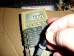
I have several of these older but good meters and they all reproduce mirror results and that's a good test.

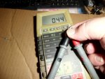
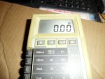
I do wiggle the probes connections and rel zero the meter before testing, I did see 0.33 change to 0.13 - 0.12 and the light went from pitiful to much better.

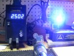
A good MX-900 single cell draws 2.2 amps at 4 volts.

My good single cell single XML-l2 draws 2.8 amps from 1 cell ( 4 volts )

This draws 4.9 amps from 4 cells in parallel ( 4 volts ) after my repairing the limiting resistors as it is now.

I think I am right where it's designed to be or just slightly less, it's not 7 times what my good XML-L2 puts out but it is twice as bright, where before it was just even.

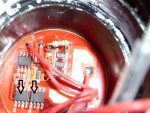
Edit-------The video said stock is 35 watts and I am only drawing 20 watts, but his is an earlier model and his limiting resistors are 0.05

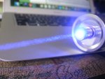
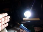
I use the dark bathroom lighting up the white ceiling test and I look at the walls to judge room brightness and it is twice the light of the L2, too bad it's not 7 x the brightness. But I know it doesn't work that way, however the leds have plenty left in the tank, the drivers I think may be near their factory limit, I'm not sure, I heard they are 6 amp drivers in this video below.

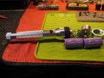
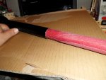
p.s. I used short 12ga solid copper jumpers to bypass the tail cap switches and get inductive current readings, but I did not have a 3rd hand for the camera, lol.

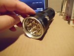
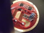
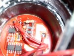
In this video the guy says the drivers are 6 amp, I see 2 are common to one poll going to the 7 led head on my board, the other chip I think is the control chip for the modes.
I wonder if I could heat sink the chips and lower the limiting resistors some more.

53378d1476149141-c-cell-maglite-notice-sany0739b.jpg


You can skip ahead to 8:00 for the technical.


Attachments

  • SANY0756.JPG
    SANY0756.JPG
    192.3 KB · Views: 27
  • SANY0758.JPG
    SANY0758.JPG
    182.5 KB · Views: 20
  • SANY0766.JPG
    SANY0766.JPG
    193.9 KB · Views: 19
  • SANY0739b.JPG
    SANY0739b.JPG
    159.3 KB · Views: 43
Last edited:

Benm

0
Joined
Aug 16, 2007
Messages
7,896
Points
113
Do those chips get hot during normal operation of the light?

One thing that is a bit of a 'lucky factor' in this whole setup is that the forward voltage of the leds is very close to the supply voltage, so not much has to be dissipated in these drivers to begin with.

Also the voltage drop over the leds rises with increasing current while the battery voltage drops a bit as well, giving them very little to do.

If you powered this light from a rock solid 5 volt supply you'd likely blow those current drivers up or send them into thermal shutdown if they have that (i reckon they do).

If you could be bothered: could you measure the voltage at the battery terminals and that across the leds when running on this thing? I reckon the difference is tiny which is why those tiny ic's can do their job without heatsinking (or even any effort to do so with pcb copper areas/vias/etc).
 
Joined
Jul 10, 2015
Messages
9,907
Points
113
I added 2 more 1 ohm resistors in parallel dropping it to 0.1 ohms and the chips are fine, not hot at all after 1 minute on, it works great, the leds get 2.73 volts so I don't know how low the batteries can get but I expect these mosfets are low dropout so I will recharge around 3.25?

They are 4 good quality LG INR 3000mAh cells. So there won't be much sag with 12000 mAh on tap, I could probably go to 0.05 as was pictured in the video, also he said stock was 33.5 watts in, I was drawing 4.9 amps at 4 volts when it was 0.125 ohms, now it's 0.1 so maybe 25w in and his board only had 1 chip mine is a later model and has 2 parallel, it's dated as being made just months ago.

They are switching transistor chips without an inductor but seem to be pretty efficient, stock was 3 x 0.33 in parallel so 0.11 ohms and I am at 0.1 so I think I will be just fine, so far I only run it a few minutes and it's not but a little warm, I popped out the board and touched the chips and they were not hot., The board was barley warm at the edges where it sinks.

Like you say they are not working very hard, supposedly they are good for 6 amps each, I am doing maybe half that tops.


Top