- Joined
- Nov 7, 2008
- Messages
- 5,725
- Points
- 0
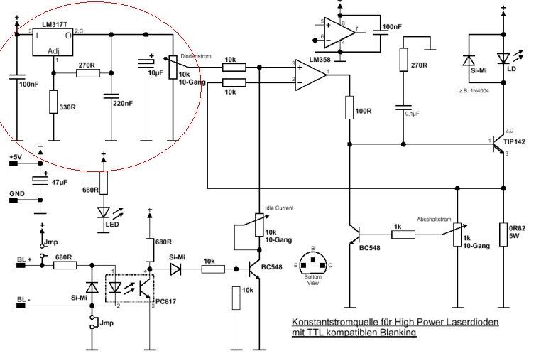
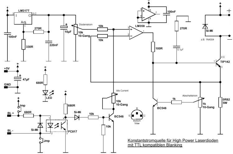
You're definitely right.. that's not a usable schematic, and I didn't intend for it to be. It's just the only fast way I could think of to help you visualize what needs to be done in order to see some decent modulation rates.. The circuit design and fine tuning is up to you..
Personally I recommend using the schematic I posted on reply #24. It contains all the necessary elements to safely modulate up to 20kHz I believe.. All you need is a few common components (resistors, diodes, transistors), an op-amp and an optocoupler.
As I said previously, if you just replace the LM317 portion of the circuit (red circled portion below) with any standard DDL circuit and just add the rest to it starting with the 10k pot directly after, it simplifies the circuit even more.
That circuit will allow for safe fast modulation and I don't think it can be done as cleanly with any simpler circuitry. Don't let the apparent complexity fool you. If you look closely, you'll see that it's really not much at all.


