Welcome to Laser Pointer Forums - discuss green laser pointers, blue laser pointers, and all types of lasers

LPF Donation via Stripe | LPF Donation - Other Methods

Links below open in new window

ArcticMyst Security by Avery

Blackbuck 8M Driver Heat Sink Advice

Joined
Jun 30, 2018
Messages
3
Points
0
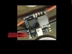
I purchased a blackbuck 8m driver for a NUBM44-81 diode (7W).

I will probably not run to the upper power limit, but the intended application is a homebrew laser engraver, so it will likely be on for long enough that a heat sink on the driver would be prudent. I have space and cooling air available.

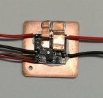
I have seen one recommendation for a 14mm heat sink on the "bottom" of the driver, but this doesn't make much sense to me - it seems like it should be attached directly to the regulator chip. The thing I like about the bottom is that it will be easier to keep it in front of the cooling fan while still potentially keeping reasonable access to the current limit adjustment pot, but don't want to cook it while cooling the wrong part of the device.

Anyway, any advice or success story regarding a robust cooling solution would be much appreciated.


Joined
Sep 20, 2013
Messages
17,253
Points
113
Most of these drivers have particularly dense traces and are heat sinked to copper mostly, from the bottom. That is the most efficient way to heat sink a driver now. But, you must also be aware of any through hole contacts that can short out against the host. Most people use thermal tape to cover the bottom of the board and either use a thermal adhesive or the adhesive from the thermal tape to make to good thermal connection to the module's back or a pill or some other part of the host.
 
Joined
Jun 30, 2018
Messages
3
Points
0
Both of these responses were super helpful!!!
Thanks much, I feel a lot better about sinking from the bottom and will heed the warnings about shorting.
I like the copper sinks, I will probably use them instead of aluminum.

I appreciate the quick replies!
 
Joined
Jun 30, 2018
Messages
3
Points
0
Okay, I guess I didn't think too much about the Pi sinks only being 5mm tall - they look bigger in the picture :)
I'll probably just start with a nice big aluminum sink on the back and watch the temperature.
I should be able to mill the sink to avoid the through hole connections and properly insulate electrically.

Again, thanks for the quick and helpful reply!
 
Joined
Jul 10, 2015
Messages
9,799
Points
113
You don't need the thermistor, if you are not using an additional pot you must use a switch or a jumper between the 5V reference and ground, and along the way I think they changed the 3 tabs as for what's what, so depending on which edition you have it's different, it's the bottom two but used to be the first two like in this pic of one I bought early on.

61144d1533717711-blackbuck-8m-driver-heat-sink-advice-sany0203b.jpg


conn_butt.jpg
 

Attachments

  • SANY0203b.JPG
    SANY0203b.JPG
    87.6 KB · Views: 44
Last edited:
Joined
Feb 2, 2012
Messages
577
Points
43
The Blackbuck 8M runs very hot even at 4.5 Amps. I can't imagine it could ever run for more than a few seconds at 8 Amps.


This is how I did the heatsinking on my Nubm44 Lab Style build. There are 2 Heat pipes from the 2 IC's to the main sink. The Copper sink was thermally bonded to the diecast case it was all put in. It should run forever at 4.5 Amps.

I did put a Pot on the modulation input so I could adjust the output.
 

Attachments

  • 57934d1508234939-my-nubm44-build-blackbuck-81.jpg
    57934d1508234939-my-nubm44-build-blackbuck-81.jpg
    93.4 KB · Views: 42
Last edited:
Joined
Sep 20, 2013
Messages
17,253
Points
113
I have the same BB drivers you do, Chris. I hope I don't have problems with mine when I use them. The astralist driver gets very hot too at 4.5 amps. One reason I bought the BBs was to mitigate the heat issue with the astralist driver. I am getting concerned about using these drivers at 4 to 5 amps now. :undecided:
 

toromand

New member
Joined
Sep 17, 2019
Messages
5
Points
3
I know this is an old thread, but the questions are related...
What is finally your result of running the controller 4.5+ Amps?
I'm making the same build one of these days so I am concerned.
Also, as I will use external PWM I will not use the 5v out for adjusting Laser power - so is it safe to hook up a small 30mm fan to it?
 

Anthony P

Well-known member
Joined
Oct 7, 2018
Messages
529
Points
63
I have done several project using the BB8M. I used kapton tape on the heatsink and arctic silver to glue the driver to the tape/sink.

I cannot answer your question about using the 5V terminal to power your fan. Personally, I would run the fan from the pre-driver voltage source.
 

toromand

New member
Joined
Sep 17, 2019
Messages
5
Points
3
Thx for the prompt reply!
I was thinking of using a thermal pad and screws to fix the driver to the alu heatsink.
Did you use any heatsink(s) on the top side (components)?
About the fan - yes I will find a suitable 12v 30mm fan and hook it up to the 12v driver source. I was just wondering about the 5v ref current limits.
 
Joined
Jan 29, 2014
Messages
12,031
Points
113
I had an objection to heat sinking through the PCB, didn't like it, but was told it was designed to do so, although the contacts can be a problem if you don't tape over them. They aren't a perfect design in my mind, but can work out well if properly mounted. I later found a way to place additional heat sinking on top of the chip, but it was also mounted to a heat sink on the bottom side too.
 
Last edited:

toromand

New member
Joined
Sep 17, 2019
Messages
5
Points
3
I guess putting a thermal pad underneath the whole board should be enough to electrically insulate the contacts. If I understand well, thermal pads (I have some Chinese blue ones) should work fine covering both insulation and heat transfer.
 
Joined
Jan 29, 2014
Messages
12,031
Points
113
I've used those pads before, not as good as something like Arctic Silver, or perhaps thermal epoxy, but may work out OK, if you use the thin ones. I believe they come as thin as .5 mm. I seem to remember this driver has a thermal cutoff at 140 C, if too hot, so at least won't destroy itself if it isn't enough.
 

toromand

New member
Joined
Sep 17, 2019
Messages
5
Points
3
Talking about Arctic Silver, did you tape-cover the whole board or just the input/output pads?
 
Joined
Jan 29, 2014
Messages
12,031
Points
113
I put black tape over where the contacts were as added protection, but didn't really need to do so because I used small square of copper between the board just below the chip and a larger heat sink under it which was small enough to keep from pushing against the tape. Not ideal, but worked out fine. I had compressed another small piece of copper on top of the chip down to hold the whole assembly tightly together. The driver was sandwiched between heat sinks, top and bottom, with a hole drilled through the top to allow me to get to the current limit adjustment pot.
 

Anthony P

Well-known member
Joined
Oct 7, 2018
Messages
529
Points
63
Talking about Arctic Silver, did you tape-cover the whole board or just the input/output pads?
I Kapton taped the heat sink only and used the arctic silver epoxy directly on the board. The epoxy is an electrical insulator when cured.


Top