Welcome to Laser Pointer Forums - discuss green laser pointers, blue laser pointers, and all types of lasers

LPF Donation via Stripe | LPF Donation - Other Methods

Links below open in new window

ArcticMyst Security by Avery

Blackbuck 6 Momentary Switch Question

Ricker

0
Joined
Oct 14, 2015
Messages
626
Points
63
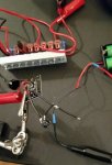
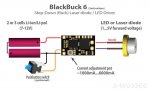
Hey everyone, I have a quick question about installing my momentary switch on my Blackbuck 6 Driver. I have installed it exactly like x-wossee has it in the diagram. When I went to test it with my test load, for some reason when I pressed the momentary switch down, it turned the current off to the test load and DMM, and turned it back on when I let off of the switch. I know the switches legs that are pointed towards each other are connected, and the others are not connected until pressed. I confirmed this with my DMM as well. So I know the legs I'm using are correct.
Am I an idiot and reading the diagram wrong, thus wiring it wrong? It doesn't seem to make sense due to the current being able to bypass the switch all together the way I have it wired currently.
Is it only meant to be wired like this using an ON/OFF switch as he has shown?
If so, is it possible to run the momentary switch i am currently using in line with just the single ground wire going to the driver, or is that not okay due to too high amperage?
Thanks for everyone's time and help!
 

Attachments

  • wiring.jpg
    wiring.jpg
    68.2 KB · Views: 80
  • bb6.jpg
    bb6.jpg
    43.2 KB · Views: 176


Joined
May 30, 2016
Messages
964
Points
0
Open is on by default. That would leave closed to being off. Right? In other words if you just didn't use that feature and hooked it up like usual it would work and those pads would be an open circuit. If closing the circuit powers it down then there you go that's how it works. If the driver requires you to solder bridge those two pads if not in use then I'm completely wrong.
 
Last edited:
Joined
Sep 20, 2013
Messages
17,443
Points
113
Looks like a TTL input to me. That would make a high, on, and ground, off. I'm not familiar with this driver though, so maybe someone who is will chime in.
 

Ricker

0
Joined
Oct 14, 2015
Messages
626
Points
63
Open is on by default. That would leave closed to being off. Right? In other words if you just didn't use that feature and hooked it up like usual it would work and those pads would be an open circuit. If closing the circuit powers it down then there you go that's how it works. If the driver requires you to solder bridge those two pads if not in use then I'm completely wrong.
It is closed DISCONNECTED by default, only open CONNECTED when it's pressed.

Edit: I have the closed and open backwards, I wasn't thinking.
 
Last edited:
Joined
May 30, 2016
Messages
964
Points
0
It is closed by default, only open (connected) when it's pressed.

http://www.aecsensors.com/html/a-push-button-switches.html

88.jpg


I think you want a normally closed (N.C.) momentary switch if when you complete the circuit the laser turns off. That way when you press the switch button the switch will disconnect (open) the circuit and the laser turns on. If your host has a tail cap button it would act as an arming switch.
 
Last edited:

BobMc

0
Joined
Apr 23, 2016
Messages
3,685
Points
113
dden is correct you need a "normally closed" switch. His explanation is on point. Good explanation dden. :)
 
Last edited:
Joined
Sep 20, 2013
Messages
17,443
Points
113
This is just how a TTL input would work. I think that is what it is. If it has 5 VDC on the pad with the switch open, that would clinch it. The switch grounds the pad bringing it 0 VDC.
 
Joined
Jun 14, 2017
Messages
452
Points
63
Ya know, I was wondering this myself. Thanks for asking the question, Ricker!! And for all others' input, too😀
 

Ricker

0
Joined
Oct 14, 2015
Messages
626
Points
63
My terminology was backwards it is only connected when pressed.

So that means I do have exactly what you're saying Dden, how is it shutting off when i press the button down, closing the loop? And could I just run it in line with JUST the ground, making it work that way?
 
Last edited:
Joined
Sep 20, 2013
Messages
17,443
Points
113
My terminology was backwards it is only connected when pressed.

So that means I do have exactly what you're saying Dden, how is it shutting off when i press the button down, closing the loop? And could I just run it in line with JUST the ground, making it work that way?

That pad is like a TTL input. When it is high (5 VDC), it is on. When it is low (ground), it is off. The switch grounds the pad that seems to float at 5 VDC. That is why it won't work the way you want it to. To use it you will have to find a switch that opens the circuit when it is pushed. Hope that makes sense to you.
 
Last edited:
Joined
Apr 6, 2014
Messages
2,436
Points
113
That pad is like a TTL input. When it is high (5 VDC), it is on. When it is low (ground), it is off. The switch grounds the pad that seems to float at 5 VDC. That is why it won't work the way you want it to. To use it you will have to find a switch that open the circuit when it is pushed. Hope that makes sense to you.
I would think that switch may have both N.C and N.O contacts wouldn't it?
If so, he can solder it to the appropriate contact.

einstein.gif
 
Joined
Sep 20, 2013
Messages
17,443
Points
113
It's a tactile switch. Most have only push to connect, but some momentary switches do have a double throw configuration. You would have to choose your switch carefully in order to get that effect.


Top