Welcome to Laser Pointer Forums - discuss green laser pointers, blue laser pointers, and all types of lasers

LPF Donation via Stripe | LPF Donation - Other Methods

Links below open in new window

ArcticMyst Security by Avery

big problems with sharp 185 mW 638 nm diodes

DTR

0
Joined
Jun 24, 2010
Messages
5,684
Points
113
Lets start here.

I have only one question to DTR: Do you test the diodes before you sell them, and if yes, how do you test them?

Yes the process on bare diodes is to use one of the three diode testers Lazeerer set me up with which are X-DRive minis with diode stockets ont en them. 150mA/350mA/1A which is enough to get any diode i carry above lasing except the case positive/case negative diodes which thankfully I only carry tree currently that become a pain. AFter they go right in the ESD. Auggie packed this so to be clear I did not see it myself but it got done. That does not mean something did not happen going tin the packaging, during shipping or whenever. One would be rare two pretty unlikely.


my consequences from this waste of money:


I think you might have the idea I was trying to catch you in a gotcha your fault moment and missed where I said "I can help ease the pain but lets get to the bottom of what happened." which I did not fullly spell out but maybe was missed.

These are the threads that add so much value to this community actually troubleshooting fails. I am not worried about a couple diodes and would gladly make you whole and to me that is well worth the cost of creating valuable content that may guide others or even give you some food for thought on ways builds can go bad saving others from similar experiences.

Most the time this will not give a 100% that is what happened but the process of going over everything is how we learn and share. I am guessing you might have misjudged my enthusiasm in your exact process with the intentionally vague replies to the specific questions I had asked.


I agree with Paul that it is a good probability the driver and diodes are two separate issues. Anyway if you are willing to go over it for me pictures would be great.

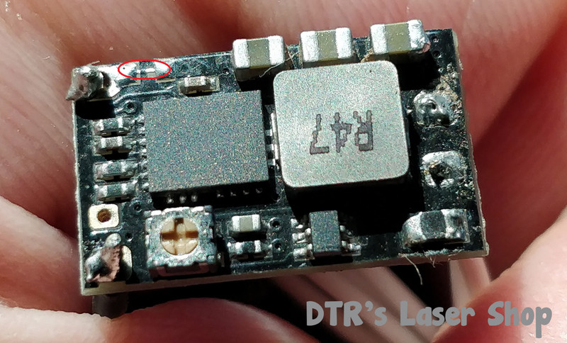
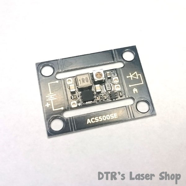
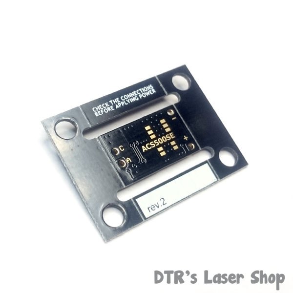
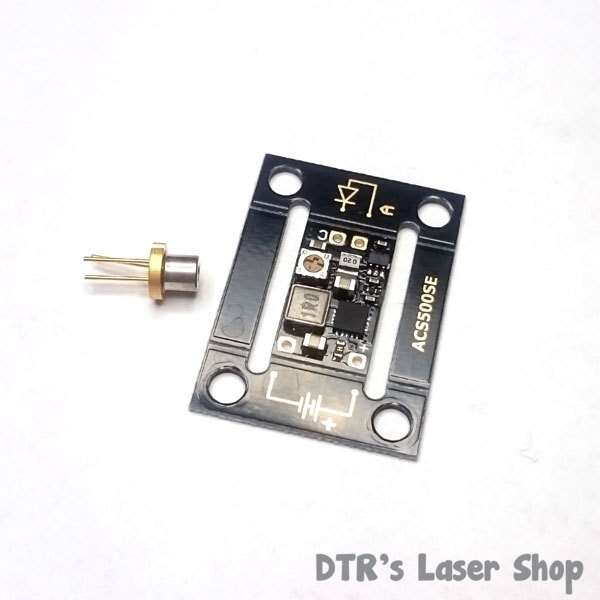
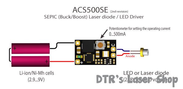
The driver guessing it is either LDS500SE or ACS500SE? If so or not which specific one. A pic of the front and back showing its current state. There are some common things that I have seen which with these sepic drivers does not trigger it to turn on. I don't believe the output being open or would damage it as if the voltage of the source or forward is not in spec it will just not activate the driver. These are very different than say the SXD where they just operate out of regulation.

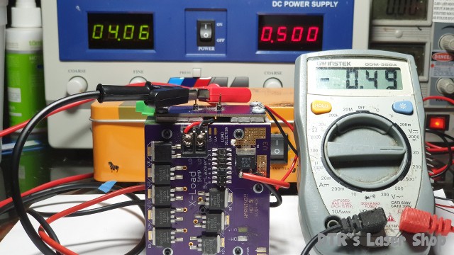
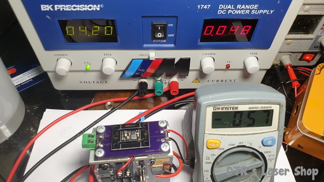
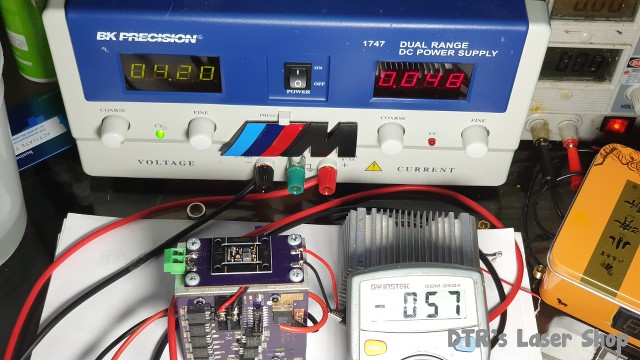
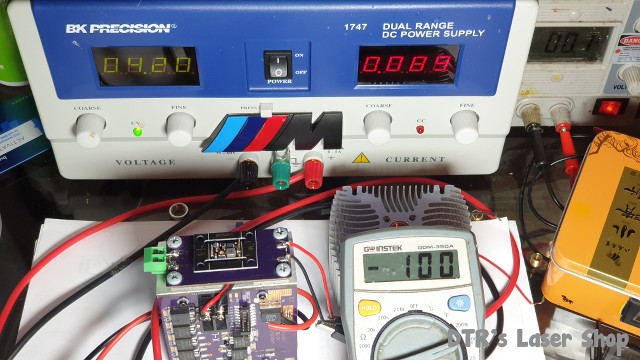
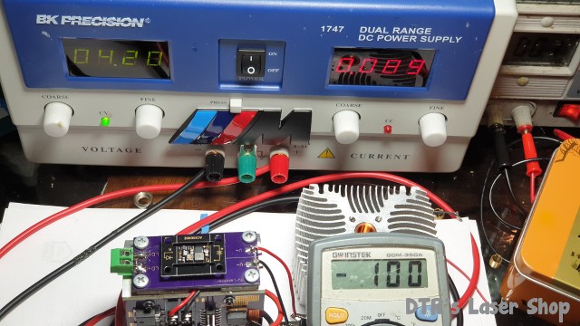
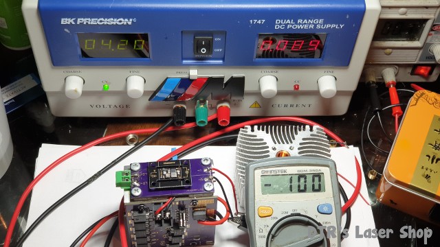
On the power supply I see this a lot "laboratory supply" does not give any info and again based on the same intentionally vague reply when I asked about it you might have thought I was looking to blame you or something. The model(a picture would be great) showing the style. Independent voltage/current control. Analog, Digital and specific process and setting on the unit from beginning to end of the process of powering the diodes.. I will probably sacrifice a diode making a video showing what I was trying to describe but any supply I have used if voltage is set to 2V or more even with the current set to zero cause instant LDD with the 638nm sharp and oclaro SM/MM diodes. Something about them.


reloader45

Active member
Joined
Mar 17, 2019
Messages
172
Points
28
Hello,

the Driver is an ACS500SE. It also will not work with my dummy load. I am not sure, if x-wossee tested every Driver he shipped.

Do you like to see Pictures of the Driver, is that correct? I will check the Driver today with my USB microscope. Then, i will wire up the Driver again with my dummy load, if I can not see a defect or broken part before.

You are right, meanwhile I also think, that the problem started with a bad driver and got worse when I decided to test the diodes with my laboratory power supply. I am not sure, but it is possible, that this power supply has a capacitor in the outlet. That would give a current Peak to the Diode, if the voltage is higher, than the diode Needs.

I like the idea with the test device, with a socket for the Diode. I will build this with LM 317 Drivers without any capacitor.
Is it possible to test a Diode with 100 mA for some seconds without a heatsink?


best regards

Edgar
 

DTR

0
Joined
Jun 24, 2010
Messages
5,684
Points
113
On the driver yea when you get a moment just a regular pic of both sides as long as you can see it clear. Just had a conversation with a guy last night which was pretty common on this one as he was thinking his BB6 was dead. Finally sent a pic and immediately spotted a common thing with them. The zero ohm resistor that can be removed and a on/off switch added came off assume when he was soldering leaving the driver deactivated. Never knwo if someting simle an extts set of eyeballs can catch.


Here is what I have on the ACS500SE's


I don't think thes
 

reloader45

Active member
Joined
Mar 17, 2019
Messages
172
Points
28
Hello,

attached some photos of the driver. I am also in contact to x-wossee.
Some contacts of the IC look poor.

best regards

Edgar


driver 2.jpgdriver1.jpgdriver3.jpg
 

DTR

0
Joined
Jun 24, 2010
Messages
5,684
Points
113
Can't see any immediate issues with the driver. How about the power source and the voltage drop of your simulated load. You can test the load directly on your lab supply to get the exact forward voltage at the current you will be using by just by connecting the supply directly to your simulated load and use current regulations to the current you will be using. and what you see on the voltage being pulled is your exact as they do charge quite a bit as you put more current in them and if not sinked the drop can rise rapidly as they get hot.
 

reloader45

Active member
Joined
Mar 17, 2019
Messages
172
Points
28
-Hello,

I wired the driver again and tested it with a 4 diode dummy load. The power input was 4,2 V with no current limitation.

The output was 1,1 V, zero mA. this driver is dead!
I finished my laser diode test stand with a lm 317 IC set to 125 mA. It works great with the the IC socket for the diode. I tested a lot of my remaining diodes, they all work fine. The problem is, that I have no sharp 638 nm diode left.


best regards

Edgar
 

DTR

0
Joined
Jun 24, 2010
Messages
5,684
Points
113
Was not able to take a pic of the test? A picture really just conveys what you want you are seeing and Really want to help but with so little info and what there is a bit confusing so have to give my best go. I actually got some great info tonight so will post this but if you would rather not see if thee is just something simple to get the river you already have up and running we can leave it there.

Ok so you say 4 diodes lets just guess they are rated 1V drop @ 1A. Then four of the in series 1.1V being "pulled" from the driver as the driver is current pushed and the voltage is drawn based on that fixed current and its current resistance. The diode pulls and the regulator either bucks or boosts the input voltage to meet the demand. If it is dropping 1.1V there has to be some current flowing though it. If you meant you pulled the load out of the circuit and tried to read current and voltage on the output of the drive r then it might read some odd voltage with near zero current as under 2V drop the driver will turn off. It will work for something like the linear driver you built. They are very solid as the bucking and boosting cane make a lot of noise which needs to be smoothed out before giving to the diode. T?he other reason I actually very against diode sockets or any quick connect as any disconnect and poof. Lots of crappy ones on ebay. The thorlabs ones I have work sell on the testers but they are not cheap.

Anyway specs say if the load is not 2V it is below the minimum which 1.1V would be and there would be no output.

Ok since I do not know the value of the diodes you are using I went ahead and mapped out all the different settings for my load with this drive3r which uses Beefy. Mapped out jumper settings starts with one and add norre more with each higher number jumper.


Ok so for this idode I want a setting where it is over 2V with 100mA or higher so I would use number five for this.

Oh my in this teste I see capabilities past what Vlad rated them. check this out. first this one was preset to 50mA. Will have to keep an eye out if they all are set to 50mA or 100mA.


Here is a simulatio of the driver being powered by a single fully charged Li-ion. Jumper setting 5


Turned the driver up to 100mA as that was one possible preset current for the one you got from Vlad.


Ok so lets start dropping jumpers till we get to 100mA with a 1.1V drop or as close to as possible.
If I can reproduce what you are seeing based on the limited variables I know.


Jumper 3 100mA This is pretty standard.


DTR

0
Joined
Jun 24, 2010
Messages
5,684
Points
113
Anyway check out how low this can go and still have regulation. That Is a amazing
 

reloader45

Active member
Joined
Mar 17, 2019
Messages
172
Points
28
Hello, this was a really long answer.

But the story is very short. The driver did not work proper just from the beginning. With 4,2 V input, there is only 1,2 Volt output. That is not enough to drive the laser diode or my 4 diodes dummy load. So the resulting current is approx. zero. So it is possible, that I killed the diodes with my laboratory power supply later.
I will ask x-wossee for an refund for the defect driver.
You should be happy with this, or is x-wossee your second ebay shop?

best regards

Edgar
 
Joined
May 12, 2017
Messages
961
Points
93
Hello, this was a really long answer.

But the story is very short. The driver did not work proper just from the beginning. With 4,2 V input, there is only 1,2 Volt output. That is not enough to drive the laser diode or my 4 diodes dummy load. So the resulting current is approx. zero. So it is possible, that I killed the diodes with my laboratory power supply later.
I will ask x-wossee for an refund for the defect driver.
You should be happy with this, or is x-wossee your second ebay shop?

best regards

Edgar
I could see DTR tried to provide all he could,But I seem you think he is denying responsibility,The diode dies directly from the lack of knowledge about your electricity, you can't blame anyone,you might come up and test the diver with a led or a testload before attaching it to the diode, that's how experienced people have stated here.

I really do not want to deepen your pain, I know the feeling of losing a pile of money in a moment, but the way you handle a problem really makes me unhappy, even though I'm just an outsider, consider this an expensive lesson for you, you should be careful in your next builds, and remember that laser diodes are very easy to die
 

DTR

0
Joined
Jun 24, 2010
Messages
5,684
Points
113
EDIT
Was getting a little brain fried last night, Was a long day. Cleaned up some near unintelligible rambling.

OH wrong video. This alone blew me away. 2.3V in 100mA out on and the load based the the mapping data only 0.35V.o_O


Sorry as I mentioned in my last it is not really an "answer" or directed toward your specific setup as still have not seen what you have and not sure exactly what you are trying to describe.

Well just move on if you are good. I generated some great content for this driver. Maybe you find it useful or give insight to you or others. Vladimir(X-Wossee also Know as Bbe on the other forum based out of Russia) he designs and supplies laser drivers that I have that I have found to be very good quality and is an indispensable supplier of laser drivers especially now as I am not sure if any more Lazeerer drivers are coming our way. 😢

I have no skin in this game at the moment as they are not in my shop for sale right now. In the future no doubt based on this testing.


Hello, this was a really long answer.

But the story is very short. The driver did not work proper just from the beginning. With 4,2 V input, there is only 1,2 Volt output. That is not enough to drive the laser diode or my 4 diodes dummy load. So the resulting current is approx. zero. So it is possible, that I killed the diodes with my laboratory power supply later.
I will ask x-wossee for an refund for the defect driver.
You should be happy with this, or is x-wossee your second ebay shop?

best regards

Edgar


I am sure he will work something out for you.

No worries probably just something lost in translation or a common misconception when trying to wrap around current source in a voltage source worLd. Good the testing showed under 2V still worked so if your load only dropping 1.1V should've come on like the video did.🍺
 
Last edited:

reloader45

Active member
Joined
Mar 17, 2019
Messages
172
Points
28
Hallo thrinh hong phuoc,

I think, you did not read my answers well.

It is not important what you think about what I may mentioned!

Just read what I wrote in my last answer. Also, I did not like what you wrote about my abilities. As you are not direct involved into this story, you should keep calm.
Next time I will handle such problems only by PM.

best regards

Edgar
 

reloader45

Active member
Joined
Mar 17, 2019
Messages
172
Points
28
Hello,

I had good conversation with X-Wossee. He will send my a new driver.

best regards

Edgar
 
  • Like
Reactions: DTR
Joined
Feb 25, 2010
Messages
1,643
Points
113
Hmmmmm...This Thread is both educational….and....Entertaining !!! About 6mo ago...I fried a
Sharp GH0637AA2G....just on a bench supply......Forgot to dial down the current....OR....had an intermittent contact....Not sure
....POOF !!! DUH !!! CRAP !!!
These Red's are the most sensitive Bastard's !!!
Take-away....we all make mistakes....well...I do !!! Sometimes COD is our fault....sometimes NOT.....Sometimes we know what we did wrong....Sometimes....we do not.
Faulty Bench Supply, Bad diode, Bad Driver....or bad settings.....one of the aforementioned !! Who knows.... It is painfull….but....not unusual.
To me...it sounds like both DTR and Wossee are standing behind you....for the sake of Goodwill....This is admirable.....
Good Luck.
CDBEAM
 

reloader45

Active member
Joined
Mar 17, 2019
Messages
172
Points
28
Hello,

at the Moment I build a laser Diode tester from LM317 IC with 3 current steps from 120 mA to 240 mA.
I will power the tester with a 18350 cell and magnetic contacts.
Power on is made with a push button to run the uncooled Diode only for the split of a second. I am waiting for the IC test socket to connect the laser Diode to my test device. So I am sure, that I will not kill further diodes during function control.

I do not think , that this posting is Entertainment.


best regards

Edgar
 
Joined
May 12, 2017
Messages
961
Points
93
Hello,

at the Moment I build a laser Diode tester from LM317 IC with 3 current steps from 120 mA to 240 mA.
I will power the tester with a 18350 cell and magnetic contacts.
Power on is made with a push button to run the uncooled Diode only for the split of a second. I am waiting for the IC test socket to connect the laser Diode to my test device. So I am sure, that I will not kill further diodes during function control.

I do not think , that this posting is Entertainment.


best regards

Edgar
A small note is never connected like picture, if you use capacitors they will kill your LD quickly
grrgr.png


Top