Welcome to Laser Pointer Forums - discuss green laser pointers, blue laser pointers, and all types of lasers

LPF Donation via Stripe | LPF Donation - Other Methods

Links below open in new window

ArcticMyst Security by Avery

Bicron Surveyor M mod - PIC scaler BIG POST

Joined
Jul 4, 2008
Messages
2,499
Points
113
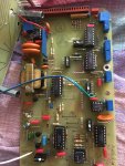
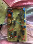
Over the past few weeks I have been probing my Bicron Surveyor M for useful areas in which to pull digital pulses from to trigger a number of different ICs and boards. The Bicron Surveyor M is a very compact Survey meter that can be used with a multitude of different probes from GM detectors, proportional detectors and scintillation detectors. Voltage settings from 0 - 2kV and can run from a single 9V battery. (2x9v in parallel) if you happened to have the scaler option on the meter (rare).
It turns out through my examination that the pulse processor MC14538B a dual, retriggerable, resettable monostable multivibrator has an unused pin
(pin9) that outputs a ~18uSec negative pulse for each event counted.
I have tried hooking this up to a USB to serial adapter Rx to GND and GND to Rx on the adapter---> This produced pulses that were seen by a few programs
UGP, as useful pulses.. actually the output of the survey meter was great until about 450-500KCPM, but then the data rate was unable to keep up with higher count rate especially when using Scintillation detectors (usually above +1MCPM rate)

So here is the challenge. I have plans for building a PIC based scaler from the GCE Yahoo groups. A scaler pulls in pulses and counts them based on a set time variable. The longer the count time the more accurate the average counts. This scaler also enables serial communication to read the values of the measurements over 1200/9600baud serial connection.
The scaler is based on a PIC16F627A and the creator of the code for this scaler has made use of code in BASIC STAMP II. I do not have access to the PIC16F62A but instead have a PIC18F2855 already on a board (ECIO28). I have already tried modifying the basic stamp but to no avail. I think I got the wrong pins set up.
If anyone has coding ability in basic stamp II and knows how to convert the PIC16F62A code to one that'll work on the PIC18F2855

I'd really appreciate it.

I'll attach a copy of the code in text. It is not my code.
DO NOT USE IT for anything else other than modifying or adapting for a personal use project.
You'll see the commented code in the text file called Picscaler4 PBP3 commented release.

Attached is a board detail document (.pdf) outlining the circuit and board layout.
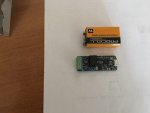
I'm using the ECIO28 board, so this takes care of a few of the parts.


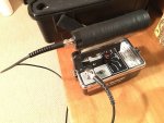
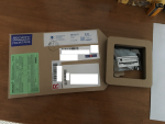
Also attached to this post are 2 pics showing the case and the Bicron Surveyor M with a BCM410 1" organic scintillation detector with the voltage set to 1.25kV.
 

Attachments

  • IMG_1603.JPG
    IMG_1603.JPG
    145.5 KB · Views: 208
  • IMG_1601.JPG
    IMG_1601.JPG
    108.9 KB · Views: 152
  • Pic scaler 4 PBP3 commented release 2.txt
    6.3 KB · Views: 141
  • PIC GMC Instructions (4).pdf
    64 KB · Views: 54


Joined
Sep 20, 2013
Messages
17,253
Points
113
Can't help with your challenge, but it looks like a very nice meter. You don't see a lot of analog meter movements any more.
 
Joined
Jul 4, 2008
Messages
2,499
Points
113
Can't help with your challenge, but it looks like a very nice meter. You don't see a lot of analog meter movements any more.

Actually after today I've decided to integrate a special PMW-Rx board made in Switzerland to the meter instead. I get the added benefit of an integrated ARM chip with own flash module, a superspeed 250Khz sampling rate and capable of 4uS resolution per pulse. ( more than fast enough to see the 17-18uS pulses generated by the MC14538B)


Yocto-PWM-Rx - USB PWM input

I am also in the process of adding a lower level discriminator to the Bicron as well. This is actually quite easy as it only involves
replacing 2 resistors, and making one of those resistors a variable resistor and removing part of a trace. this modification to the original circuit can be found on page 3 of the attached .pdf.


The pic18F2855 is going to wait until I can get better instructional material.
 

Attachments

  • MOD BIRCRON.pdf
    598.3 KB · Views: 46
Last edited:
Joined
Sep 20, 2013
Messages
17,253
Points
113
I noticed the sample rate is variable from 0.05 Hz up to 250 KHz. Is the memory part of the circuit or do you have to add that? I look forward to seeing the end result.
 
Joined
Jul 4, 2008
Messages
2,499
Points
113
I noticed the sample rate is variable from 0.05 Hz up to 250 KHz. Is the memory part of the circuit or do you have to add that? I look forward to seeing the end result.

That board has got a small amount of flash memory onboard. most of the computing is done in either Java, delphi, C+,C++ etc...

btw their Yocotovolt board is precisely what we need for building a very high accuracy LPM ( down to 0.01v ~0.5%)@ 10Hz using any of the analog ophir sensors. they're ~$75.00 USD shipped. Something like this could be easily adapted to Trevor's Peregrine. We could also add wavelength parameters to this as well! :drool:
 
Last edited:
Joined
Sep 20, 2013
Messages
17,253
Points
113
That's good news, but I don't know anyone who is trying to update an LPM platform at the moment. I'll look forward to your project instead.
 
Joined
Jul 4, 2008
Messages
2,499
Points
113
That's good news, but I don't know anyone who is trying to update an LPM platform at the moment. I'll look forward to your project instead.

Once everything has been sorted out and the mods to the bicron's motherboard have been made (adding the lower level discriminator and window ch1/2 switch) I'll then post the results with the scaler board. I plan on using an Rs232 serial port as the USB data extension plug for the computer. The second header on the board will go directly to a low profile (64bit) ARM board flashed with Linux-mint/Unbuntu ..not sure which yet.

Eventually I'd like to build in a spectroscopy system as well. (might be a bit ambitious). This depends on how noisy (how much ripple) the PSU is.
 
Joined
Jul 4, 2008
Messages
2,499
Points
113
Well a small gift arrived from Switzerland today in the form of a YoctoPMW-Rx board from yoctopuse.

54980d1488609111-bicron-surveyor-m-mod-pic-scaler-big-post-img_1687-2.png


It's tiny... I mean really tiny! Wow..
54979d1488609111-bicron-surveyor-m-mod-pic-scaler-big-post-img_1688.jpg

This is good as it makes integrating this board into my survey meter far easier.


So I gave it a test run. This board operates as it's own host and has an imbedded webpage run via loopback http://127.0.0.1:4444 (port 4444 is used as a TELNET for PIC24) The webpage contains basic settings that you can change to make each input function differently. This board is capable of processing 2 completely separate inputs simultaneously without any delay. (10Hz update of counts due to buffer)

I downloaded and installed the interface driver off the yoctopuse website, then after install I plugged in my new board I attached the signal out from the MC14538B (pin9) to the PMW input and attached another wire from survey meter GND to the GND of the board.

with the interface driver now installed I called up the page and changed input 1 to show edge counting. This counts each pulse and simultaneously measures each pulses frequency and the duty cycle. The faster the count the tighter the timings the higher the PMW frequency.

54981d1488609111-bicron-surveyor-m-mod-pic-scaler-big-post-img_1689.jpg


With a LND7317 probe attached to my Bicron M survey meter, I turned the meter to HV to make sure the HV was set to just a hair over 500v. -- I put the meter on 1x and did a count of the background and compared the meter face with the digital output.

My background using the LND7317 was any where from 45-65CPM according to the pulses logged. Over a 10 minute interval
The total counts / number of minutes gave me an averaged reading ~48.45CPM which is right about normal in our location for a detector this large.

48.45/(Cƒ x 60) = 0.01379mR/hr x10 (0.1379uSv/hr) ( Conversion factor or cƒ=58 for LND7317)

within an hour of running on 10 minute intervals our background stays within 48CPM averaged over time on this particular tube.

Using a 1.25" NaI/Tl scintillation detector set on a 1V sensitivity @ 1.1kV, our average counts is around 6-10KCPM.

last but not least I drove the LND7317 to near saturation to about 10KCPS. (600,000CPM), not only was I able to see the total pulses but I was also show the deadtime on the tube ~20uS (0.02mS) .

At a certain point a GM tube will start to lag due to the lack of time the tube has to reset its self. Eventually the tube will get to a saturation point and no longer function. Fortunately modern survey meters have an ani-sat feature to avoid this.

In rarer instances continuously running a tube in high radiation areas will lead to tube death.

below is a graph showing the deadtime and tubes sensitivity plateau (thanks to K0FF)

sen7311.jpg


So what do I need to do now to the meter...Well a bit. I need to rebuild the meters metering sensitivity and install the LLD (lower level discriminator), channel switch, window adj, and a count light. additionally I want to install the yocto PMW Rx boarding with a
ARM board to act as a further pulse processor, data logger..etc.

As you can see by my sketching. The different colours represent the areas to be modded
54977d1488609111-bicron-surveyor-m-mod-pic-scaler-big-post-myboard-.jpg

54978d1488609111-bicron-surveyor-m-mod-pic-scaler-big-post-img_1686.jpg
 

Attachments

  • myboard?.jpg
    myboard?.jpg
    314.4 KB · Views: 361
  • IMG_1686.JPG
    IMG_1686.JPG
    131.5 KB · Views: 321
  • IMG_1688.JPG
    IMG_1688.JPG
    80.7 KB · Views: 347
  • IMG_1687 2.png
    IMG_1687 2.png
    770.5 KB · Views: 390
  • IMG_1689.JPG
    IMG_1689.JPG
    107.3 KB · Views: 347
Last edited:
Joined
Sep 20, 2013
Messages
17,253
Points
113
Congratulations on the board's arrival. It looks like you have another jump in making your detector more sensitive and increase its resolution. I see it is a work in progress and I am looking forward to the next post on this project.
 
Joined
Jul 4, 2008
Messages
2,499
Points
113
Congratulations on the board's arrival. It looks like you have another jump in making your detector more sensitive and increase its resolution. I see it is a work in progress and I am looking forward to the next post on this project.

There is a very excellently put together document by George Dowell (K0FF)
There are a few details missing which I wish would be in the .pdf, naturally these would make the mods easier to accomplish. I've already modified the spare battery area to hook to an 8.4V RC Lipoly cell or other cells up to 9.3V.

I've attached the .pdf instructional for modifing the Bicron Surveyor M into an Analyst 2000.

:thinking:
 

Attachments

  • bicron2000-analyst2000-Toto4G.pdf
    598.3 KB · Views: 51
Joined
Mar 25, 2016
Messages
475
Points
0
Not trying to sound arrogant here but didn't your microcontroller come with a manual?

--EDIT--

Have you looked into Rasberry Pi? Its a very versatile and cheap mini computer
 
Last edited:
Joined
Jul 4, 2008
Messages
2,499
Points
113
Not trying to sound arrogant here but didn't your microcontroller come with a manual?

--EDIT--

Have you looked into Rasberry Pi? Its a very versatile and cheap mini computer

Not sure which microcontroller you are referring to.

I've got a PIC18F2455 (ECIO24P) and the Yocto PMW-Rx.

The yocto PMW Rx doesn't come with a manual but you've got to download it. The ECIO28P comes with a tiny manual...
I'm still working on the PBP3 Pro program which is outside of the ECIO28P compiler/editing capabilities.


The Raspberry Pi is a nice single board computer but it lacks an ADC. This fact makes it useless on its own.
The Yocto PMW Rx has 2 dedicated high speed ADCs (PIC24F) capable of seeing the frequency, pulse width, edge counting down to 4uS simultaneously.


I've attached a .PDF showing the underside of the Bicron main PCB
and the top. I've included labels for everything.
 

Attachments

  • Board TOP&BOTTOM.pdf
    587.9 KB · Views: 48
Last edited:
Joined
Sep 20, 2008
Messages
17,622
Points
113
From what you stated.. the original program was to
run om a PIC16F27/28 and PIC16F62Awhich is in the
PBP3 capabilities.
Why do to want to use a PIC18F2455 ?
If it's due to cost/availability... Digikey in the USA can
get you a PIC of your choice to you in 24 hours at
a reasonable cost with only $8.00 Cnd. Shipping.

Jerry
 
Joined
Jul 4, 2008
Messages
2,499
Points
113
From what you stated.. the original program was to
run om a PIC16F27/28 and PIC16F62Awhich is in the
PBP3 capabilities.
Why do to want to use a PIC18F2455 ?
If it's due to cost/availability... Digikey in the USA can
get you a PIC of your choice to you in 24 hours at
a reasonable cost with only $8.00 Cnd. Shipping.

Jerry

Actually, thats a good question. I originally opted for a prefab board namely because it already had a USB port built in, so as to skip the programming board all together. I also wanted to have a look at running some other programs on it before dedicating this device (integrating it) into the Bicron. I've discovered that in my experimentation that the onboard oscillator crystal needs changing from 4Mhz to a 20Mhz one.

PBP3 is also fully compatible with PIC18F2455 and most other PIC18s.

However, while playing with the PIC, I discovered a PIC24 based board that does exactly what I am looking for and is already programmed specifically for high speed PMW.
It's a great deal faster and can process 2 channels simultaneously.

This project is evolving.. many things to do physically to the board and then once those are cleared and working I'll add the scaler and processing portion of the board. One mod at a time. ;)


An aside, another interesting discovery.. Some of the more modern "smart" survey meters can overcome GM tube deadtime by adjusting/ turning on and off the PSU at exactly the given deadtime of the tube.
LND7311 and the 7317 both have 20uS dead times. Pancake tubes generally have lower dead times than cylindrical tubes.
 
Last edited:
Joined
Jul 4, 2008
Messages
2,499
Points
113
A further bunch of experiments this past week has revealed yet some more interesting functions of the Yocto PMW-RX.

Slight correction from before. This board is actually running a PIC24FJ64GB, not an M4 as previously mentioned.

The Frequency reported back from the PMW software = CPS. I tried a strong Uraninite sample that I measured with my LENI-CDV700 with my scaler attachment. I got 96,522 CPM using a (900V) 7311 (pancake a+B+y probe)
This is equal to 1608.7 CPS, or what the Yocto PMW RX sees as 1.6087Khz on the Bicron. (quite a reproducible count rate)
Simultaneously the software sees 193,044CPM as it is edge counting. What I need to do is divide the edge count by 2 and make the frequency in Hz reported back as CPS (Counts per second). Edge counting counts both the peak and the 0 state as a single event.
Each pulse therefore is a 2 value.

I have 2 complete channel inputs to play with on the board.

What I do see now is that the internal analog metering on the Bicron Surveyor M accuracy falls off dramatically on the 1000x setting. At 11.110Khz reports as 800,000CPM according to the Bicron Manual, yet this translates real world into 666,600CPM and at 3.175Khz (200,000CPM on the Bicron) and real world = 190,500CPM. I believe the incongruency is due in part by the dead time on the tube that the meter was calibrated with. With a Scintillation detector there is no deadtime to factor in to speak of , just the lower threshold of the detector in mV. right now it is set at ~1V input which is too high to detect the 32KeV gamma on a NaI/Tl detector.

Now the trick is to write software to interface with the board that will take
the output of this device ( make the necessary changes) and graphically display the output/ datalog it.
 
Last edited:


Top