- Joined
- Jul 4, 2008
- Messages
- 2,499
- Points
- 113
Over the past few weeks I have been probing my Bicron Surveyor M for useful areas in which to pull digital pulses from to trigger a number of different ICs and boards. The Bicron Surveyor M is a very compact Survey meter that can be used with a multitude of different probes from GM detectors, proportional detectors and scintillation detectors. Voltage settings from 0 - 2kV and can run from a single 9V battery. (2x9v in parallel) if you happened to have the scaler option on the meter (rare).
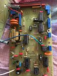
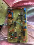
It turns out through my examination that the pulse processor MC14538B a dual, retriggerable, resettable monostable multivibrator has an unused pin
(pin9) that outputs a ~18uSec negative pulse for each event counted.
I have tried hooking this up to a USB to serial adapter Rx to GND and GND to Rx on the adapter---> This produced pulses that were seen by a few programs
UGP, as useful pulses.. actually the output of the survey meter was great until about 450-500KCPM, but then the data rate was unable to keep up with higher count rate especially when using Scintillation detectors (usually above +1MCPM rate)
So here is the challenge. I have plans for building a PIC based scaler from the GCE Yahoo groups. A scaler pulls in pulses and counts them based on a set time variable. The longer the count time the more accurate the average counts. This scaler also enables serial communication to read the values of the measurements over 1200/9600baud serial connection.
The scaler is based on a PIC16F627A and the creator of the code for this scaler has made use of code in BASIC STAMP II. I do not have access to the PIC16F62A but instead have a PIC18F2855 already on a board (ECIO28). I have already tried modifying the basic stamp but to no avail. I think I got the wrong pins set up.
If anyone has coding ability in basic stamp II and knows how to convert the PIC16F62A code to one that'll work on the PIC18F2855
I'd really appreciate it.
I'll attach a copy of the code in text. It is not my code.
DO NOT USE IT for anything else other than modifying or adapting for a personal use project.
You'll see the commented code in the text file called Picscaler4 PBP3 commented release.
Attached is a board detail document (.pdf) outlining the circuit and board layout.
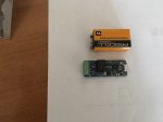
I'm using the ECIO28 board, so this takes care of a few of the parts.
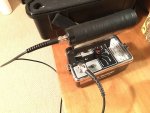
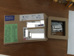
Also attached to this post are 2 pics showing the case and the Bicron Surveyor M with a BCM410 1" organic scintillation detector with the voltage set to 1.25kV.


