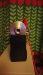
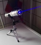
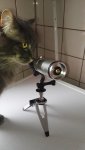
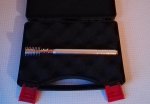
Very nice build Enchilada. :gj: Lovely cat BTW.

+rep :beer:
agree!!
Found this very helpful... some here may want to start using a laser driver every time--even if the own a $$$$ Bench power supply -the authors are with a company that makes/sells PS so if anything, they would be biased and not be advising us to use a driver, even a cheap one EVERY TIME__
_________________
Powering Lasers: Evaluating Bench Power Supplies
Photonics Handbook
Supplying power to a laser is delicate work because lasers are extremely sensitive and easily damaged. A single pulse of excessive current, lasting only a few microseconds, can overheat and damage the light-emitting facets of a laser diode. While a laser diode driver is the safest and most effective method for powering a laser, in some cases, a bench power supply may be an option. The answer depends on the application and on the performance of the specific bench supply in question.
PAUL CORR AND PATRICK KLIMA, ARROYO INSTRUMENTS LLC
A bench power supply should be thoroughly tested and characterized before it is used to power a laser. The quality of the controls and safety measures incorporated into a bench supply will need to be evaluated to determine whether it is suitable.
The issues of bench power supplies
1) Dangerous current control
A laser diode is inherently a current-sensitive device, requiring constant current to function properly.
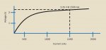
Figure 1 shows that a small change in voltage can result in large changes in current. When using a bench supply that is voltage controlled (only output voltage is adjustable), small adjustments can quickly produce unexpectedly large changes in current and easily drive the laser beyond its maximum ratings. Never use a voltage-controlled power supply.
Voltage-current performance of a hypothetical laser diode.
Figure 1. Voltage-current performance of a hypothetical laser diode.
2) Unpredictable power-up
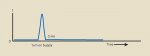
A bench power supply is unpredictable at startup (Figure 2). Even with the voltage set point at zero, initial power-up can produce a brief, but large, current spike. This spike, which can reach very high currents, may only last a few microseconds or milliseconds but can critically damage the laser.
3) Slow response time
In response to issue two, some users may be tempted to turn on the bench supply at zero volts and let it stabilize before connecting the laser. In this circumstance, the circuit is open before the laser is connected. Even though the set point is at zero, there will typically be a small voltage present. As the connection to the laser is completed, the current may spike rapidly as the supply reacts to the nearly zero impedance load. The bench supply will respond by bringing the voltage back to the nearly zero set point indicated, but that response will not be fast enough to protect the laser.
The current response for a hypothetical bench power supply at power-on.
Figure 2. The current response for a hypothetical bench power supply at power-on.
4) Limited voltage and current safeguards
The only remaining option would be to connect the laser to the bench supply with the voltage and current set points at zero. Assuming that the bench supply did not allow a current spike at power-up, the subsequent increase in voltage and current still have an inherent risk. A bench supply is not typically designed to make the transition from voltage control to current control with the necessary speed and may fluctuate enough to damage the laser. Even bench supplies with current limits will typically not be sufficiently fast to protect the laser in an overcurrent situation.
5) Other missing safeguards
Other safeguards that will almost certainly be missing from bench supplies include:
• Poor contact protection: Many bench supplies will go well beyond their current limits when the connection is restored.
• Overvoltage protection: Shutdown of the drive takes place when voltage exceeds a preset limit.
• Shorting protection: Mechanical and electrical short of the laser when the supply is off.
• Other engineered protections, such as safe shutdown on AC power failure and electrical isolation.
With all of these potential difficulties, the only way to verify whether a specific bench supply will be suitable for an application is to fully characterize its performance.
Characterizing the performance of a bench power supply
Characterizing a bench power supply requires equipment capable of measuring fast voltage and current transients while minimizing the impact on the supply performance during the measurement process. A common practice for current measurement is to place a noninductive current-sense resistor in series with the supply and measure the voltage across the resistor to derive the current. However, adding a series resistor can change the dynamics of the loop and produce a different – and inaccurate – picture of the supply performance.
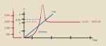
Hypothetical performance of a voltage-controlled bench power supply with a current limit.
Figure 3. Hypothetical performance of a voltage-controlled bench power supply with a current limit.
While it may not always be practical, a better choice is to use a noncontact DC current probe to measure current flow, which will not change the dynamics of the control loop and therefore not influence the measurement. In either case, an oscilloscope of at least 300-MHz bandwidth will be needed to capture any transient events. Using a current sense resistor also requires an understanding of the grounding scheme used by the power supply and oscilloscope. The ground connection of an oscilloscope is typically connected to earth ground. If the supply’s outputs are also connected to earth ground, a current loop could be created and damage the equipment. Floating the oscilloscope by disconnecting earth ground using a ground-lift plug should only be done if the operator is fully aware of the risks in doing so.
Another consideration is the load to be used during testing. Obviously, the laser itself should not be used – the whole point of characterization is to first ensure the supply is safe to use with the laser. A laser can be approximated by using high-speed rectifier diodes, with a sufficient number of diodes in series to develop the same operating voltage as the laser. Make sure to select rectifier diodes with sufficient current handling, and heat sink the devices as necessary.
The various operating conditions under which the bench supply will respond will then need to be simulated. To begin, connect a load to the power supply, and measure the current performance in the following scenarios, along with any others that may be relevant:
• Turn the power supply on and off several times.
• Start the circuit in an open condition, and then close the circuit.
• Move from one voltage and current set point to the next.
• Test an intermittent connection, such as that caused by a loose cable.
• If the power supply accepts a function generator input, test the performance of the bench supply while connected to the function generator.
• If the bench supply performs adequately under these circumstances, it may be suitable for the laser application.
When are bench supplies appropriate for lasers?
A bench power supply will typically be more successful in a high-power application (for example, with a 60-A bar laser) where power can be distributed across several light-producing facets and is therefore more tolerant of power spikes. Low-power lasers are very easily damaged and far less tolerant of spikes and poor power delivery.
In any case, careful characterization of the power supply is of the utmost importance to reduce the risk of laser damage. Ultimately, the best option may be to use a laser diode driver. A laser driver will include a variety of safeguards specific to operating a laser. Even the most inexpensive laser driver will offer superior protection, higher accuracy and better performance than a bench power supply.
Voltage-current performance of a hypothetical laser diode.
Figure 1. Voltage-current performance of a hypothetical laser diode.
2) Unpredictable power-up
*** PS
Any with questions about why diodes are NOT returnable... READ.. so many things can go wrong in a hurry.. good luck to all--hak
more or same??
having probs with the illustrations
http://www.arroyoinstruments.com/whitepapers/Arroyo-UsingBenchPowerSupplies.pdf
click to see diagrams post them for me if you can---TY


")
 .(and certainly dont got high hopes for that one, but will give some knowledge, for relative little amount)