Welcome to Laser Pointer Forums - discuss green laser pointers, blue laser pointers, and all types of lasers

LPF Donation via Stripe | LPF Donation - Other Methods

Links below open in new window

ArcticMyst Security by Avery

Basic Electronics Questions. AMC7135

Joined
Mar 29, 2013
Messages
1,221
Points
63
Hey guys! I have been looking at low cost red builds lately, and the ML101U29-25 diodes have come up ($3 per diode)

These are rated at 400mw and a perfect current for these is 350ma. Coincidentally, the AMC7135 chip puts out 350ma! In a very compact package!

Anyways, the forward voltage stated on the ML101U29-25 datasheet is 2.35 - 3 volts (typ - max) so generally will have about 2.5 fV.

I want to use one cell. Maybe a 16340 or an 18650 etc. So input voltage will be 3.9 - 4.2 volts.

I have looked and looked. So i have two questions.

The Vf of the ML101U29-25 is slightly higher than the other mitsu diodes. Will it still work with a single cell?

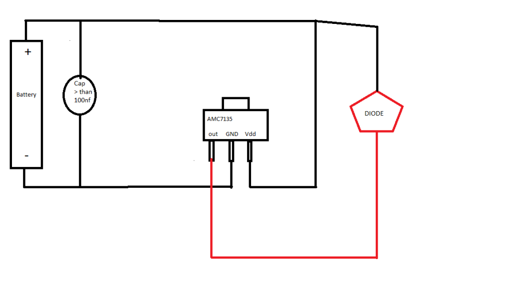
What is the pin-arrangement for the AMC7135? The three pins from left to right and the GND pin on top?

Also, if i want to make a very compact red driver out of these chips, all i would need is the chip and a diode for reverse polarity protection? Feel free to shoot me if i am being really stupid with anything i say.

Any help with this would be greatly appreciated!

Thanks
-Matt


Joined
Mar 29, 2013
Messages
1,221
Points
63
Yeah it will work have a look here:

http://laserpointerforums.com/f50/diy-little-red-key-chain-lives-pic-heavy-85709.html

This was a simple red made from a DVD drive and one AMC chip. Ill try to find a simple circuit diagram. :beer:


Edit: here you go. http://laserpointerforums.com/attachments/f44/32744d1305648834-amc7135-question-amc7135.png

Wow great! I kind of suck at reading schematics, so i have no idea what it says.

So the battery GND is attached directly to the GND tab/pin of the AMC, the battery+ and battery- are bridged with a capacitor with a value i do not know. And the diode attached to the GND and the Vout?

I just dont get why the diode in the schematic is attached to the Vout of the AMC and the battery+ where is the GND connection to the diode?

Thanks
-Matt
 
Joined
Dec 11, 2011
Messages
4,364
Points
83
The negative of the diode is attached to the out pin of the AMC7135 because it is a regulated current sink. This means it serves as the load's (diode's) connection to ground, and only lets so much current flow to actual ground (battery negative). If only so much can flow out, then that same amount can only flow in. The capacitor there is known as a decoupling capacitor and any value above 0.1uF (100nF) will do. You want either ceramic, electrolytic, or PP "film/foil" type capacitors. If you use electrolytic make sure you mind the polarity. Aside from that, the battery positive goes to the Vdd (positive) of the chip and the positive of the diode, and yes the cap goes between the Vdd and Gnd of the chip.
 
Joined
Mar 29, 2013
Messages
1,221
Points
63
DIAGRAM_zpsf67ba606.png


This is my interpretation of the the earlier provided link. Sorry i only have Paint.exe right now as i just reinstalled my OS cause my SSD failed.

Is this correct?

Is the out pin the +LD input or is the Vdd the +LD input?

Thanks
-Matt
 
Last edited:
Joined
Dec 11, 2011
Messages
4,364
Points
83
It looks correct as you have drawn it, but put the cap as close to the chip as you can. If you can put it directly across the chip between the Gnd and Vdd that is best. The more wire between the chip and the cap the worse it will perform.
 
Joined
Jul 4, 2012
Messages
2,834
Points
63
You realize they are 400mW PULSE diodes right?
CW is like 150mW for them
 
Joined
Mar 29, 2013
Messages
1,221
Points
63
You realize they are 400mW PULSE diodes right?
CW is like 150mW for them

These diodes have been tested at up to 400ma. 350ma is semi-conservative and puts out about 250mw with a G-2 lens.

So which goes to the laser diode +? The "OUT" or the "Vdd"

Also, how much do these need to be heatsinked? None right?

Thanks
-Matt
 
Last edited:
Joined
Jul 4, 2012
Messages
2,834
Points
63
I bought 10 of these chips a while back, and let me say...they are frickin small. Be prepared lol
 
Joined
Dec 11, 2011
Messages
4,364
Points
83
Diode positive goes to battery positive or Vdd (electrically identical). Diode negative goes to chip out.

The chip will need minor heatsinking for long runtimes, nothing major.


Sent from my iPhone using Tapatalk
 
Last edited:

jimdt7

0
Joined
Feb 5, 2011
Messages
1,893
Points
48
Does anybody know how can I wire two AMC chips together? :thinking:

Jim
 
Joined
Dec 11, 2011
Messages
4,364
Points
83
Multiple chips are used in parallel, so you can simply stack a second chip on top of the first one. I wouldn't stack more than two for thermal reasons though.


Sent from my iPhone using Tapatalk
 
Joined
Jan 29, 2012
Messages
3,164
Points
113
Yup just put one on top of the other and attach with some thermal epoxy. Then solder a bridge between the pins. Dont worry about the middle pin as there is more room to connect that at the back of the chip (GND).Did this a while back to get near 6 A out of an AMC 3.05 A board! Also did some other mods on the same board to run an MT-G2 at 8.4 V. If you want further info Ill look up the relevant threads. :beer:
 
Joined
Mar 29, 2013
Messages
1,221
Points
63

jimdt7

0
Joined
Feb 5, 2011
Messages
1,893
Points
48
@KRNAZNBOY I'm also in the process of designing my own driver...good luck my friend! :beer:

Jim


Top