Welcome to Laser Pointer Forums - discuss green laser pointers, blue laser pointers, and all types of lasers

LPF Donation via Stripe | LPF Donation - Other Methods

Links below open in new window

ArcticMyst Security by Avery

Anyone familiar with Attiny13 programming?

rhd

0
Joined
Dec 7, 2010
Messages
8,475
Points
0
Is anyone familiar with Attiny13 programming and willing to give me a half hour or so of time in exchange for.... I don't know, something laser related, or some money?

I basically want:
- to have someone covert a program that I'll write in basic generic code (consisting mostly of if/then logic, a button press, a single memory read/write, generation of a random number, output on a couple pins, and then, perhaps the only tricky part, generation of a pwm signal with a couple different duty cycles)
- the ability to ask some questions along the way, so I can fast track my own process of getting up and running to program chips.


ARG

0
Joined
Feb 27, 2011
Messages
6,772
Points
113
If you're familiar with Arduino it's not too hard to port Arduino code into something compatible with Atmel Studio 6 for programming other AVR's.
 

rhd

0
Joined
Dec 7, 2010
Messages
8,475
Points
0
If you're familiar with Arduino it's not too hard to port Arduino code into something compatible with Atmel Studio 6 for programming other AVR's.

I'm not, unfortunately.
 
Joined
Dec 11, 2011
Messages
4,364
Points
83
I've never worked with the 13s but I've worked with the 85s, arduinos, and C++ in general. Go ahead and shoot me whatever questions you have and I'll help if I can. I'll pull up the ATT13 datasheet in the mean time.

Initial look over shows it to be a less capable version of ATTiny85, having only 1kB of memory. If your program looks to be something I can comfortably handle I'll help with porting it to the more capable ATT85 as well. The reason I suggest this is that the myriad of functions you are suggesting in your summary eat up programming memory. I've done similar projects to this as well (see my site section on the ATTiny Interrupter and my blog page on Arduino real-time HiFi audio pwm (not midi crap sound!).
 
Last edited:

rhd

0
Joined
Dec 7, 2010
Messages
8,475
Points
0
Well, I'm not invested in ATTiny13, other than the $5 or so I spent on ICs. I think the same USB AVR Programmer I ordered will work for ATTiny85:
NEW 1pc USB ISP Programmer FOR Atmel AVR Atmega Attiny 51 Development Board | eBay

I'd be happy to use ATTiny85 if you think it's a better chip for me to learn. I think the code is different, so it probably makes sense for me to figure out something useful from the start.

I don't think the program I want to write is too deadly, but maybe I'm being unrealistic. Here's the program I want to write (no particular language - just trying to convey the logic). I'm sure you can tell what I'm trying to do here :)

---------------------------------------------

Code:
on chip startup {

   call MainProgram

}


on button press {
   
   MemoryVariable = MemoryVariable + 1

   IF MemoryVariable > 9 THEN
        MemoryVariable = 1
   END IF

   Call MainProgram

}


MainProgram {

   IF MemoryVariable is unset, THEN
        set MemoryVariable = 1
   END IF

   If MemoryVariable = 9 THEN
        ColorChoice = random digit from 1 to 7
   ELSE 
        ColorChoice = MemoryVariable
   END IF

   IF ColorChoice = 1, THEN
        Pin1Output = set it high
        Pin2Output = set it high
        Pin3Output = set it high
   ELSE IF ColorChoice = 2, THEN
        Pin1Output = set it high
        Pin2Output = set it low
        Pin3Output = set it low        
   ELSE IF ColorChoice = 3, THEN
        Pin1Output = set it high
        Pin2Output = set it high
        Pin3Output = set it low
   ELSE IF ColorChoice = 4, THEN
        Pin1Output = set it low
        Pin2Output = set it high
        Pin3Output = set it low        
   ELSE IF ColorChoice = 5, THEN
        Pin1Output = set it low
        Pin2Output = set it high
        Pin3Output = set it high        
   ELSE IF ColorChoice = 6, THEN
        Pin1Output = set it low
        Pin2Output = set it low
        Pin3Output = set it high        
   ELSE IF ColorChoice = 7, THEN
        Pin1Output = set it high
        Pin2Output = set it low
        Pin3Output = set it high        
   ELSE IF ColorChoice = 8, THEN
        Pin1Output = Generate PWM at roughly 200 Hz, with 50% duty cycle
        Pin2Output = Generate PWM at roughly 200 Hz, with 50% duty cycle
        Pin3Output = Generate PWM at roughly 200 Hz, with 50% duty cycle     
   END IF

}

---------------------------------------------

EDIT: I actually care the least about the PWM output - so if that's challenging, I'd just drop it.
 
Last edited:
Joined
Dec 11, 2011
Messages
4,364
Points
83
These Atmel chips cannot run multiple programs or timers simultaneously* (not counting special cases like using Micros() as a timer), so the button press has to be nested into the main program. This is easy and won't mess anything up. You won't be able to do the three-pin PWM off the top of my head, though I never tried on an ATT. It will be easy to test and then if it doesn't work just chop off that subroutine. Also, they automatically load and begin the main program upon powering up. a Void Setup(){} function can be used to designate initial conditions that are specific to startup in addition to the required role of delcaring inputs/ouputs.


Should be no problem at all to implement this program. Did you need examples of the formatting required? In other words, how much help do you need specifically where? =)

edit: ohh and that ISP AVR should work fine. I just use ardiuno as an AVR ISP.
 
Last edited:

ARG

0
Joined
Feb 27, 2011
Messages
6,772
Points
113
It's also worth noting that if you don't have hardware debouncing for the switch you should do it in the firmware.

I recommend reading/skimming some of these threads and trying to build as much of the code on your own :)
 

rhd

0
Joined
Dec 7, 2010
Messages
8,475
Points
0
I don't anticipate the button press occurring during the main program running though. The main program is presumably going to complete its execution in a billionth of a second, long before anyone would press the button.

For the button press, couldn't I just tell it to pause for 100ms or something like that after the end of that function? Wouldn't that take care of bounce?

Sigurthr / ARG: Your time is probably more valuable than this task justifies. I was kind of envisioning that this would be a task for some ambitious new member, who maybe was cash poor, but would be able to tackle the task in trade for a diode, or something along those lines, that I could toss in their direction.

I can figure this programming task out on my own, but there are just so many things I want to learn, and so little time, that I thought I would see if anyone wanted to tackle it in trade for something. I'd feel too guilty with you guys helping out, because you're both super busy with other projects too.
 

ARG

0
Joined
Feb 27, 2011
Messages
6,772
Points
113
The main program is just an infinite loop, just runs the same set of tasks over and over. The duration of a button press is longer than one iteration of the main program, so the main program will pick it up when the state changes.

For bounce I usually just do a multiple reads. A delay would also work.

I can figure this programming task out on my own, but there are just so many things I want to learn, and so little time

I know the feeling. My list of things I want to learn / skills I want to acquire is always getting longer.
 
Last edited:

rhd

0
Joined
Dec 7, 2010
Messages
8,475
Points
0
The main program is just an infinite loop, just runs the same set of tasks over and over. The duration of a button press is longer than one iteration of the main program, so the main program will pick it up when the state changes.

Got it. So my random function needs some revision or it will just rapidly change colors, probably imperceptibly. But that's no big deal.

I presume that once a pin is set high, it stays high though, is that the case?

EDIT: It looks like this code probably has all the pieces I'll need:

http://budgetlightforum.com/node/31126
 
Last edited:
Joined
Dec 11, 2011
Messages
4,364
Points
83
As ARG said, on uC's the entire programming is one program that runs over and over in an infinite loop. There's many ways to debounce, you can do a simple delay, but during that delay timers won't update (aside from millis()) and pins won't be read or written to (including pwm!). You can simply make a counter variable that updates when the switch pin is read as high and require multiple counts before action is taken. This allows the program to cycle without interruption and doesn't involve having to use a complex millis() counter/timer.

Code:
void Loop(){
  if digitalRead(ButtonPin, HIGH){
    ++ Pincount;
  }
  if PinCount >= TriggerCount {
    ++ MemoryVariable;
    PinCount = 0;
    if MemoryVariable >= 9{
      MemoryVariable = 1;
    }
  }
  if MemoryVariable == 8{
    ColorChoice = Random(1, 7);
  }
  Else {
    ColorChoice = MemoryVariable;
  }
  // If ColorChoice == 1 through 7 Then digitalWrite(Pins, HIGH); stuff here 
}

There, that's with the memoryvar adjusted to remove the PWM section, a working pseudo-random that triggers on 8th press, a debounce that is tunable with TriggerCount, memoryvar resets on 9th press, and if you hold the button down it will cycle through colors at a rate determined by the loop time divided by the value set for TriggerCount.

Edit: Ohh and don't feel bad, I wouldn't offer to help if I couldn't spare the time to. Besides, I am cash strapped, haha. =P
Edit 2: left out the pincount reset accidentally. That's what I get for spending all of 5mins on it.
 
Last edited:

rhd

0
Joined
Dec 7, 2010
Messages
8,475
Points
0
Okay, that's very cool. Is that code that will run on the attiny13? 85?

Any interest in perhaps filling out the rest of the program (ie. the pin stuff, memory writing, etc) and maybe answering a couple questions about loading it onto an IC (later, when my stuff arrives) in exchange for a 9mm 445? (Or something else?)

I presume something more than just writing the variable is required to make the variable persistant so that it stays set through power up/down ?
 
Joined
Dec 11, 2011
Messages
4,364
Points
83
I can flesh out the rest of the program no problem, just not tonight. I can help with any other questions you might have too.

I'm not interested in a diode, but I could certainly use a single 16340 LiIon CV Boost Converter if you're up for designing one. Just need 5V output, only has to supply 200mA, if it has built in low voltage cutoff to protect the LiIon that would be fantastic. I'm not asking for the physical circuit either unless you feel like it, just the schematic and files I'd need to submit it to OSHpark or similar. Also, if you know of a place I can get a single 16340 battery holder that would be fantastic. If you feel like making it with variable output voltage 5-14V and increased current capacity, that's icing on the cake. All through-hole construction please (unless you want to make the board yourself). I've been making a lot of portable devices lately and I hate using primary cells. I've no experience making DC-DC converters, at least not low voltage stuff (I did a 5 to 400V @ 10mA one a while back), and I generally don't do small footprint designs. I mostly work with power electronics in the kW range.

You declare and initialize variables in Void Setup (), and what you initialize them as will remain constant for all power-ups. Doing this is better than declaring them as constants because a constant is set in the compiler stage and is thus unable to be changed by the program. Using constants for variables means having to use twice as many variables.

Initializing would be:
Code:
Void Setup();
  A = 1;
  B = 2;
}

and to do the same with constants would be:
Code:
const A = 1;
const B = 2;

Void Setup();
 C = A;
 D = B;
// then you use C and D as variables
}

Edit: Oh, yes that code will run on any of the ATT uC's. You have to do some finagling to get the pin declarations right but that's it. I have it written down somewhere what physical pin actually coincides with what PortB pin which coincides with what numerical pin in code. It is totally not straight forward. I was something like PhysPin 3 = PB2 = Pin4. Totally ludicrous and drove me mad when working it out.
 
Last edited:

rhd

0
Joined
Dec 7, 2010
Messages
8,475
Points
0
If you don't mind me making the board for you, I can put one together fairly easily based on the CC-Boost. I'd just backtrack the design a bit and take out the CC functionality to revert it to CV (which is really how that IC was originally intended to be used). The only reason I say you'd need me to make that, rather than just supplying the design, is that the IC is not easy to order from Digikey, and it's SMD, not through hole.

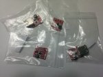
Now... that said.... I actually use single lithium ion to 5V boost converters all the time, I was going to make my own, until I found out how inexpensive they are to just buy. In fact, a whole bunch more arrived in the mail today:

attachment.php


Would those work? Want me to send you some? It turns out that if you need CV instead of CC, it's really easy to find pre-made circuits that are tiny. It's CC where we tend to need to create our own for LD driving.

16340 holders are also easy :)

Battery Holder: CR123A Battery Holder with Easy In-Out battery insertion & removal - RoHS Compliant
USD $ 3.99 - DIY 1-Slot 3V CR123A/16340/17335 Lithium Battery Holder With Pins - Black (2 PCS), Free Shipping On All Gadgets!
DIY 1-Slot 3V CR123A/16340/17335 Lithium Battery Holder With Pins - Black (2 PCS) - Free Shipping - DealExtreme

Ditto on those - let me know if you want some, I'll order them to your address.

----

Regarding the variables... I have been assuming that ATTiny chips had some sort of persistent memory that would survive power off. IE, that there would be a way to write a variable such that if it powered down with MemoryVariable set as 5, when it started back up, MemoryVariable would be 5 again (or at least there would be a way to restore it to 5). Am I mistaken about that?

EDIT: looking at the specs for the ATTiny85, I see that I'm going to need to drop the voltage down to < 5.5 volts from the 8.4V two supply voltage I was otherwise going to feed it from. Would there be anything wrong with just sticking 5x diodes ahead of the IC to drop ~3.5V, or would I need to actually add a voltage regulator to my circuit? I'm hoping not, as I'm pushing the space constraints already.

For some context, here is how the ATTiny (blank area represented by the pink square) fits into my overall project:

RGB_driver.png
 

Attachments

  • IMG_20140812_235404.jpg
    IMG_20140812_235404.jpg
    69.7 KB · Views: 415
Last edited:
Joined
Dec 11, 2011
Messages
4,364
Points
83
If you don't mind me making the board for you, I can put one together fairly easily based on the CC-Boost. I'd just backtrack the design a bit and take out the CC functionality to revert it to CV (which is really how that IC was originally intended to be used). The only reason I say you'd need me to make that, rather than just supplying the design, is that the IC is not easy to order from Digikey, and it's SMD, not through hole.

Now... that said.... I actually use single lithium ion to 5V boost converters all the time, I was going to make my own, until I found out how inexpensive they are to just buy. In fact, a whole bunch more arrived in the mail today:

...

Would those work? Want me to send you some? It turns out that if you need CV instead of CC, it's really easy to find pre-made circuits that are tiny. It's CC where we tend to need to create our own for LD driving.

16340 holders are also easy :)

Battery Holder: CR123A Battery Holder with Easy In-Out battery insertion & removal - RoHS Compliant
USD $ 3.99 - DIY 1-Slot 3V CR123A/16340/17335 Lithium Battery Holder With Pins - Black (2 PCS), Free Shipping On All Gadgets!
DIY 1-Slot 3V CR123A/16340/17335 Lithium Battery Holder With Pins - Black (2 PCS) - Free Shipping - DealExtreme

Ditto on those - let me know if you want some, I'll order them to your address.

Haha, I knew you'd be the guy to ask. You didn't list any specs for the off the shelf converters, but if they satisfy 3.7V -> 5V @ 200mA then I'd say they'd do just fine. They probably don't have LiIon overdischarge protection but if the battery holders will accepted a protected 16340 then it is a moot point. Yes, I'd def love a batt holder to go along with it if you decide to send a physical circuit. Thanks!

Regarding the variables... I have been assuming that ATTiny chips had some sort of persistent memory that would survive power off. IE, that there would be a way to write a variable such that if it powered down with MemoryVariable set as 5, when it started back up, MemoryVariable would be 5 again (or at least there would be a way to restore it to 5). Am I mistaken about that?
There's no on chip runtime addressable/modifiable memory in any of the Atmel AT family uC's (not even arduino!). You flash the chip when you program it with the AVR ISP and nothing persists after that.

EDIT: looking at the specs for the ATTiny85, I see that I'm going to need to drop the voltage down to < 5.5 volts from the 8.4V two supply voltage I was otherwise going to feed it from. Would there be anything wrong with just sticking 5x diodes ahead of the IC to drop ~3.5V, or would I need to actually add a voltage regulator to my circuit? I'm hoping not, as I'm pushing the space constraints already.

For some context, here is how the ATTiny (blank area represented by the pink square) fits into my overall project:

RGB_driver.png

Other than the obvious low voltage issue when the cells are discharged the only problem you run into is that clock speed is dependent upon input voltage. So the program won't cycle through in the same amount of time if the input voltage isn't held steady. Generally speaking you'll never see a uC without a dedicated Vreg. Since the ATTs require such low current and you're only sourcing current to a high impedance input you could use Zener regulation or a super tiny SMD linear reg. Don't forget the current limiting resiston on the button line, decoupling cap for the uC, and also you left out a ground connection on the ATT.

I have an ATT85 sitting in my drawer that I've been meaning to flash with new software at some point. Since I have to overwrite what's on there, I'll give the finished program a go and test it out as well. I can't promise I will be able to do so at a set time, but it isn't like it would be hard to fix any software issues on the fly either (as opposed to testing a physical design where you'd need testing done asap).
 
Last edited:

rhd

0
Joined
Dec 7, 2010
Messages
8,475
Points
0
Haha, I knew you'd be the guy to ask. You didn't list any specs for the off the shelf converters, but if they satisfy 3.7V -> 5V @ 200mA then I'd say they'd do just fine. They probably don't have LiIon overdischarge protection but if the battery holders will accepted a protected 16340 then it is a moot point. Yes, I'd def love a batt holder to go along with it if you decide to send a physical circuit. Thanks!


There's no on chip runtime addressable/modifiable memory in any of the Atmel AT family uC's (not even arduino!). You flash the chip when you program it with the AVR ISP and nothing persists after that.


Other than the obvious low voltage issue when the cells are discharged the only problem you run into is that clock speed is dependent upon input voltage. So the program won't cycle through in the same amount of time if the input voltage isn't held steady. Generally speaking you'll never see a uC without a dedicated Vreg. Since the ATTs require such low current and you're only sourcing current to a high impedance input you could use Zener regulation or a super tiny SMD linear reg. Don't forget the current limiting resiston on the button line, decoupling cap for the uC, and also you left out a ground connection on the ATT.

I have an ATT85 sitting in my drawer that I've been meaning to flash with new software at some point. Since I have to overwrite what's on there, I'll give the finished program a go and test it out as well. I can't promise I will be able to do so at a set time, but it isn't like it would be hard to fix any software issues on the fly either (as opposed to testing a physical design where you'd need testing done asap).

They can do 200mA no problem (they're rated for 1A, which I think is a bit generous, but 200mA is no problem). They sort of have over discharge protection in that they don't run with less than 2.5V :)

You'll need to pm me your address.

Re the lack of memory - shoot! That really puts a kink in my plans. I thought the ATTiny had an EEPROM with some trivial amount of storage. How do guys use these chips to make led drivers that remember modes after power off, if there's no non-volatile memory?

Regarding all the stuff that is missing on my pink block, that was really meant as a conceptual block, not as a stand in for the chip itself. I figured there would be some additional external components to incorporate. I will look into finding a tiny fixed 5v regulator in something like a SOT 89 package. I'm sure that exists.

There's absolutely no rush on this. The fabrication of physical parts for this particular project is months from being complete.


Top