Welcome to Laser Pointer Forums - discuss green laser pointers, blue laser pointers, and all types of lasers

Buy Site Supporter Role (remove some ads) | LPF Donations

Links below open in new window

FrozenGate by Avery

An idea for a MOSFET driver

Johnyz

0
Joined
Jul 19, 2010
Messages
421
Points
0
So, as I finally managed to find an empty projector (the one we love extracting Nichia LD's out of) (also, thanks, Greg!), I tried to find a driver for the precious Phlatlight PT-54 red LED. Now, since I was intending to use it with a 5V 10A supply, I needed a driver, that needs less voltage for itself (DDL needs additional 3V+ above the diode forward voltage). I also needed the driver to handle a high current (set it to about 8 amps and something, to be safe).

CandlePowerForums came with a nice thread.:
Super-Simple Power MOSFET Linear Current Regulator

Oh, and by the way,
88x31.png

This work is licensed under a Creative Commons Attribution-Noncommercial-Share Alike 3.0 License.

Image from the original thread:
MOSFET_Current_Regulator_web.gif


If you don't need the PWM in, just leave the part with the blue/grey background out, and it will work without it.

For my red beast, I just replaced the parts with some more power ones: the megaohm resistor for a 2W one, the current set resistor for three 0,22 ohms 20W (so we get 0,073 ohms and 60W) and the transistor for BU508A. The MOSFET can be also replaced for a IRF3205, just to be safe.

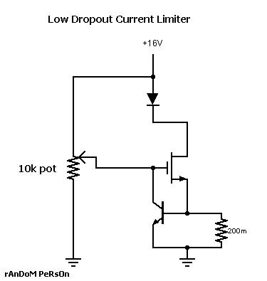
Now, where my idea lies, if we could add a capacitor or two, and replacing the resistors with one that limits the current, to, say, 1.5A and a multi turn pot we all know from DDL drivers, we could be driving laser diodes, am I right?

The problem is, that power is being pushed through the current set resistor (and through our pot), so, unless we use just one precalculated resistor, we couldn't probably drive a 445 LD at its maximum amperage, but I still think this would be nice to drive a LPC or some similar LD's from a single Li-Ion.

DISCLAIMER: I do not take credit for the circuit, I only came up with ideas that are written under the picture. I also do not take responsibility if you blow any electronic parts, or injure somebody! EVERYTHING DONE AT YOUR OWN RISK.


Sorry if these are stupid questions but..
we couldn't drive a 445 with it because the pot could overheat? can a voltage comparator be used to solve this issue?
and.. whats the dropout? have you tested it? ;)
 
If we calculate the resistance needed: R = V/I thus R = 0,68/1 = 0,68 ohms for 1 amp, 0,68 volts because we use the voltage most transistors start to open, use different if its datasheet suggests it, it's usually 0,68 volts, we can just use R2 of the proper value and no pot. I have not tested the exact dropout, but it is just a couple of millivolts, it depends on parts used.
 
Last edited:
I think the circuit looks sounds - its a textbook 2 transistor current source with the passing element replaced by a mosfet. I've had very good experiences with this circuit using bipolar transistors.
 
Please help me understand how this is supposed to work...
I've wired a IRF610 mosfet with a test load of 4*1N4001 and 1ohm resistor. When testing voltage across that resistor, I'm only getting .03 volts.

If I understand correctly...
Volts in (+) goes to the Gate and the Load
The Load (-) goes to the Drain
The circuit is grounded through the Source

Thanks for your help,
 
I've designed a simillar driver, featuring the multiturn pot. I think this version was designed for currents up to 1A, but I'm not sure now
 

Attachments

  • driver_sch.png
    driver_sch.png
    1.9 KB · Views: 9,913
Last edited:
I've designed a simillar driver, featuring the multiturn pot. I think this version was designed for currents up to 1A, but I'm not sure now

I guess I’m just confused with what I’m supposed to connect to what for this mosfet to actually boost the power. If I am not using TTL or Pulse or anything like that. I have just one (+) input and just one (-) ground.
I thought these schematics made sense, but I’m getting confused because it’s not working… as it should… I guess. Haha!
 
What's your input voltage to the diode? The only thing the circuit does is regulate the current. It doesn't boost voltage or anything like that, and the current sense + mosfet can use 1-2V depending on the values and current.
 
What's your input voltage to the diode? The only thing the circuit does is regulate the current. It doesn't boost voltage or anything like that, and the current sense + mosfet can use 1-2V depending on the values and current.

I’m using a single 18650 Li. At the moment, the output is 4.03 Volts. Is a mosfet not what is used in a boost driver to get 4 volts to power a 6 volt diode? Or are those just barely providing enough voltage at 4 volts?

Say I need to power a diode rated for 5Volts at 3Amps. The mosfet’s datasheet says it has a guaranteed 3Amp regulation and I would like to use a single 18650. How would I boost the voltage in the circuit for the diode? Thanks.
 
The dropout is the transistor base emitter voltage i think, so it's around 0.68V usually.
 
I have used this Mosfet circuit several times.

There are some cautions required when using this circuit.

The base to ground diode is heat sensitive.

It starts out @ ~ 0.6 VDC and drops with temperature.

So you must test with heatsinking in place,

and bring everything up to operating temp to set final current.

LarryDFW
 
Last edited:
Is a mosfet not what is used in a boost driver to get 4 volts to power a 6 volt diode? .
NO, A boost regulator uses 'Switched' DC fed to an inductor to 'boost' the voltage, via induction, and usually charge a capacitor. Theload then draws from the cap. The MOSFET is a pass element. Does not boost or amplify anything (beyond, maybe, the gate current...).


Say I need to power a diode rated for 5Volts at 3Amps. The mosfet’s datasheet says it has a guaranteed 3Amp regulation and I would like to use a single 18650. How would I boost the voltage in the circuit for the diode? Thanks.

Get a BOOST regulator (Driver), like a MicroFlex, from Flaminpyro.
 
So, as I finally managed to find an empty projector (the one we love extracting Nichia LD's out of) (also, thanks, Greg!), I tried to find a driver for the precious Phlatlight PT-54 red LED. Now, since I was intending to use it with a 5V 10A supply, I needed a driver, that needs less voltage for itself (DDL needs additional 3V+ above the diode forward voltage). I also needed the driver to handle a high current (set it to about 8 amps and something, to be safe).

CandlePowerForums came with a nice thread.:
Super-Simple Power MOSFET Linear Current Regulator

Oh, and by the way,
88x31.png

This work is licensed under a Creative Commons Attribution-Noncommercial-Share Alike 3.0 License.

Image from the original thread:
MOSFET_Current_Regulator_web.gif


If you don't need the PWM in, just leave the part with the blue/grey background out, and it will work without it.

For my red beast, I just replaced the parts with some more power ones: the megaohm resistor for a 2W one, the current set resistor for three 0,22 ohms 20W (so we get 0,073 ohms and 60W) and the transistor for BU508A. The MOSFET can be also replaced for a IRF3205, just to be safe.

Now, where my idea lies, if we could add a capacitor or two, and replacing the resistors with one that limits the current, to, say, 1.5A and a multi turn pot we all know from DDL drivers, we could be driving laser diodes, am I right?

The problem is, that power is being pushed through the current set resistor (and through our pot), so, unless we use just one precalculated resistor, we couldn't probably drive a 445 LD at its maximum amperage, but I still think this would be nice to drive a LPC or some similar LD's from a single Li-Ion.

DISCLAIMER: I do not take credit for the circuit, I only came up with ideas that are written under the picture. I also do not take responsibility if you blow any electronic parts, or injure somebody! EVERYTHING DONE AT YOUR OWN RISK.

Someone licensed that circuit? har har...

Put a 10k or a 100k pot where R4 is and your good to go.... Also tie W4 to W1 if your not planning on PWM.

Edit: ... theres a better way to do this... will post when I get home from work. Pot idea wouldn't be the best right there.
Edit2:
zz-1.jpg
 
Last edited:
Trying to get analog modulation / adjustable current will not work very well by making a resistor divider between R1 and a resistor replacing the modulation part.

It does -work- , but it does not really regulate anything. What you are basically doing is dropping the bias voltage to below what is required to make the regulator work, and just letting the mosfet supply whatever it can from the base voltage.

This may be acceptable though: The maximum current is still safely limited and stable, but the down-adjusted current is unpredicable and depends on temperature and gain of the mosfet (but it will never exceed the maximum current).
 
NO, A boost regulator uses 'Switched' DC fed to an inductor to 'boost' the voltage, via induction, and usually charge a capacitor. Theload then draws from the cap. The MOSFET is a pass element. Does not boost or amplify anything (beyond, maybe, the gate current...).

Get a BOOST regulator (Driver), like a MicroFlex, from Flaminpyro.
Ahh... then I totally misunderstood the purpose of a mosfet? I thought it was used for amplifying?

Haha that would be great and all, but I want to learn how to build one and build my own... for fun! :)


Back
Top