Welcome to Laser Pointer Forums - discuss green laser pointers, blue laser pointers, and all types of lasers

Buy Site Supporter Role (remove some ads) | LPF Donations

Links below open in new window

FrozenGate by Avery

650nm 20x diode at 600ma?

Thats just too cool! Here I've been concentrating on a Blu-Ray to mount on my CnC and your using a LOC. Never even considered using red to burn with. What driver are you using? And how are you blanking it. I thought about using a switch on my Z to power it but it looks like you are not using a Z motion. I hope your willing to share the details, I've been working on this project for a while now. Nice CNC by the way...

Chuck

EDIT: I just read your website...Nice work on the software and drivers. I understand the blanking.
 
Last edited:


I'm using a BD9703 buck converter in current regulation mode as the LD driver (one of these that I described here: http://translate.google.com/transla.../_hv/index.php?page=lasers/ld_drv&sl=pl&tl=en ). That IC has a standby input pin that I use for turning the laser on and off and also to control the power with PWM signal. I'm using Mach3 software to control my CNC machine, the laser is connected to additional LPT output pin that is configured as a step line of the spindle. I use PWM control setting for spindle motor and the PWM base freq set to 1kHz (see the attachment). That allows me to turn the laser on with M3 or M4 g-code commands and off with M5 command, and also control the laser mean power with pulley ratio setting (i.e. I can set 5% of power for positioning without burning all around :) ).
 

Attachments

  • mach.jpg
    mach.jpg
    94.2 KB · Views: 801
Last edited:
Wow! I never thought about using a spindle control. Makes alot of since though. I'm using a breakout board that pulls the PWM for spindle control out to a header. So I would activate the settings in Mach and check and see if I have the voltage needed to connect to a analog driver. I think the output is 0 to 10 volts.

Is this the driver your using @600ma?

Would it be ok if I tried it using your design?
 

Attachments

Is this the driver your using @600ma?
Would it be ok if I tried it using your design?
Yes, this is it. Yes, you can use my design and since I put it on my website you don't have to ask me at all :P But I appreciate that. By the way, the IC comes from an LG DVD writer, actually the coil, shottky diode and caps too ;)
 
Hello,
I have a cnc router and I'd like to use a laser like you did.
I was wondering if you can provide a component list of your driver.
Also if you have a pdf or cad file of the circuit board, it would be great, I could cut it with my cnc machine.
How large a diode can your driver run?
I was thinking of a 2w 808nm IR diode.
Thank you and excuse me for all these questions.
 
Hi!
I'm sorry but I don't have the component list (actually I really don't understand why people ask for a component list if they have a schematic available...). I sould have the PCB design somewhere but I can't find it so at the moment I don't have it either :( The BD9703 regulator can work at max 1.5A (check it in datasheet because I may be wrong) so 2W diode is far too much. And let me ask you one thing, if you want to use such diode then do you know any trick for focusing the beam? The problem is that the emmiter in 808nm diodes is long (e.g. 100x1 um dimentions) and thus the beam divergence of one axis is differs many times to the other axis. You need some sophisticated optics to focus it OR a diode with fast axis lens already mounted.
 
Hello, and thank you for answering...
I am from Italy, I guess we are both on this side of the pond.
I am not and expert in electronics, although I have always liked the subject and I am just starting to get interested in it so I have lots to learn and read etc. I have taken apart some lg dvd burners but found no trace of the bd9703, nor could I find it in the local electronics store. They do have the LM2576-adj which seems to have similar characteristics but of course it outputs a
minimum of 3A. They have a 3.3 volt one a 5 volt one and a 12 volt one. I guess I could use the 3.3 volt or get the adjustable version, but I don't understand how to lower the 3A output current (a pot??).
I did buy a laser from O-Like which is 3.2 whatt at 808nm (220€) to hook up to my cnc machine, it's complete with focusing optics and a driver with 4 wires, red and black for a 5 volt power supply and blue and white for ttl. I don't want to start with this laser yet, I want to understand how it works by using a cheap dvd burner laser. I saw your driver with ttl and I liked it right away. Unfortunately I am not sure I can find those surface mount components. It doesn't really matter if the driver is bigger, is there a way to make a version similar to the lm317t (my current drivers) but using larger IC then the bd9703?
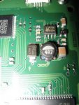
Is an Inductor needed? I think I have found a similar inductor as I saw on your driver, it has 4R7 written on it, and next to it there's a shottky diode marked 1BL3, on a Hard Disk drive. For the inductor I have found this description "Inductor, SMD series power shielded, 4.7uH, 6amps, 13m max resistance, 4mm ht", the Shottky is supposed to be 1A 30V.
the size looks similar to yours. Unfortunately, no trace of the BD9703.
I know I have written a lot and you don't have to help me of course, but I really want to build this and understand how it works and all, I've gotta start somewhere... if you could help that would be greatly appreciated, if not I totally understand. Thank you, Antonio.
 
Ok, maybe I have found the right IC it was sitting right next to the shottky and the inductor from above, it's on a Hard disk (samsung 160gb), that is burned out. It's a L5973A w/8 pins, the datasheet says it's a step-down switching regulator, with a vref, vout of 3,3v. the vin is 4,5-30V, and it works up to 2A. the pin3 is to switch the device on or off, it doesn't mention ttl, but it says that it takes a logic signal above 2,2v to switch it on and another signal lower than 0,8v to switch it off. Is this the same as TTL modulation? it mentions LOGIC, but isn't TTL an analog input? that's what I don't understand.
I am attaching a pic and a datasheet.
 

Attachments

  • small.JPG
    small.JPG
    36.3 KB · Views: 791
  • datasheet.JPG
    datasheet.JPG
    78.8 KB · Views: 1,704
Hi!
Probably you could make this IC to work as a current regulator, then it would be suitable for powering laser didoes. The LM2576 will work too. 3 amps is the max current, you can always draw less than it :) For current regulation mode you should choose version with the lowest output voltage (probably ADJ version with 1.23 or 1.25V reference voltage), because the higher reference voltage the higher power loss on the current measuring resistor. The inductor is absolutely needed here, and the larger it is the better. You always need an inductor with switching regulator (this particular regulator is i.e. 'buck converter'). But you should ask yourself a question if you really need a switching regulator. You can use almost any linear voltage regulator as a constant current source/sink and then you don't need any inductor. It's simpler and more reliable. You could even build simple current sink with TTL modulation of only three transistors and two resistors :)

the pin3 is to switch the device on or off, it doesn't mention ttl, but it says that it takes a logic signal above 2,2v to switch it on and another signal lower than 0,8v to switch it off. Is this the same as TTL modulation? it mentions LOGIC, but isn't TTL an analog input?
This is exactly what i'm using as a TTL input in my driver. It should work this way, although it may not be fast. I don't know how fast modulation you need. I think it should work for at least a few hundred Hz but if you need faster modulation (e.g. for PWM power control) you just need to check if it works.

P.S. No, TTL is not analog input. It's exactly a logic input that can only turn the laser on or off. The analog input is called 'analog input' :) When you're buying a laser module you can find in it's specs 'TTL', 'analog', or 'TTL/analog' modulation.
 
Last edited:
I have a Long Closed Can running at 510mA (in a Kryton Groove) for over 8 months. It puts out 310mW with a Virtual Village lens.

I think Igor has one (a LCC) running at 520mA

Peace,
dave
 
I have a LOC that runs at 600mA. I'm getting 340mW after a virtual village lens. Its pretty cool


Back
Top