diachi
0
- Joined
- Feb 22, 2008
- Messages
- 9,700
- Points
- 113
Things just might work out that way. Things might be working out where I might be moving farther out in the desert. And if so, Beam Shots !!!! over Death Valley.")
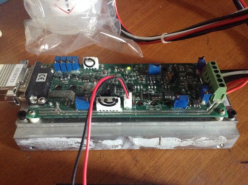
That one doesn't have the 5VDC OEM power supply does it? That'd make life a little easier for "portable" operation.