Welcome to Laser Pointer Forums - discuss green laser pointers, blue laser pointers, and all types of lasers

LPF Donation via Stripe | LPF Donation - Other Methods

Links below open in new window

ArcticMyst Security by Avery

1st laser build! Advice/info for shopping list...?

M3tal

0
Joined
Dec 9, 2010
Messages
42
Points
0
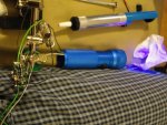
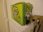
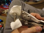
For the slightly adventurous: used vicegrips to seat the diode...

Where there's a will there's a way.

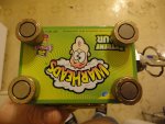
I took the attached pics after I seated the diode successfully. Wanted the pic of the module in the vicegrips for illustration purposes.

Not that I would recommend this method, but it just goes to show that sometimes you shouldn't be afraid to try creative solutions. Since it turned out to work out so well I guarantee I'll be using this method again.

I had to be careful & make a few small adjustments. But once everything was straightened fairly well it took surprisingly little pressure to seat the diode firmly in the module. I had to open up the vicegrips almost as wide as they would go to accommodate the module & wrap the paper towel pieces around the business end. Then after making sure the diode was straight as possible in the module, pressed the 2 sides together firmly by hand to get the diode to stay put temporarily. Then I laid down the 2 halves of the module in the vicegrips, adjusted the screw until the module was snug and squeezed slowly, all the while making sure to loosen my grip and adjust the module when needed to make sure the diode was going in straight.

As for the rest of the build so far:

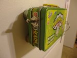
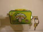
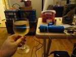
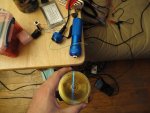
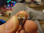
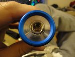
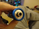
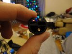
There were 2 round contacts on either side of the clicky switch. I cut off the round parts leaving only small stubs that I can solder wires to. I cut 1/4" off the top of the pill so the module would mount flush with the front of the heatsink (except for the focus ring of course, see pic) and drilled a hole in the pill to accommodate wires for the driver. As of now I have no plans to add batteries to the host... I have "other" ideas for this build. An external power source of some kind.

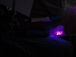
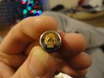
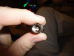
Anyway, as you can probably see in the pictures the diode isflush and seems to be seated perfectly. A complete success so far...
 

Attachments

  • Module in vicegrips.jpg
    Module in vicegrips.jpg
    129 KB · Views: 132
  • Back angle.jpg
    Back angle.jpg
    93.5 KB · Views: 120
  • Back.jpg
    Back.jpg
    93.4 KB · Views: 110
  • Module no lens.jpg
    Module no lens.jpg
    75.5 KB · Views: 143
  • Without lens.jpg
    Without lens.jpg
    101.8 KB · Views: 128
  • With lens.jpg
    With lens.jpg
    100.1 KB · Views: 117
  • Pill.jpg
    Pill.jpg
    94.2 KB · Views: 135


Joined
Nov 28, 2010
Messages
71
Points
0
Post some pics when your done! beam shot me!

OH btw quick question dude, what do you do with the case pin? are you going to attach a wire from the power source +V or -V to it? Or are you going to solder the case pin to the negative pin on the diode?
 
Joined
May 4, 2009
Messages
5,443
Points
113
You may have missed the bullet on this one but pressing on the diode
pins to put the LD in the heatsink is not a good idea. and by pressing
on the ckt board that the pins are soldered to you did just that !
You should have removed the ckt board befor pressing the LD into it's
heatsink.
and besides the LD should be pressed below the surface of the Aixiz
module and you can not do that with out a proper diode press !
A good self centering diode press will save you head aches
in the furture, get one if you plan on doing this more than a couple times !
If you had used the search button you could have found out about this
setting the diode properly. use it as it will save you cash, why repeate
the mistakes of others ;)
Have a merry xmas :san:

28ic7di.jpg
 
Last edited:

M3tal

0
Joined
Dec 9, 2010
Messages
42
Points
0
Post some pics when your done! beam shot me!

I will definitely be posting a few pics... as soon as I find a decent power source, that is. :beer:

OH btw quick question dude, what do you do with the case pin? are you going to attach a wire from the power source +V or -V to it? Or are you going to solder the case pin to the negative pin on the diode?

According to this link: I-Hacked.com Taking Advantage Of Technology - Building a High-Power Blu-Ray Laser I could solder the unused pin to the negative pin but I'm not sure what the benefit would be, so I will probably just leave it like it is. Unless someone recommends otherwise...?
 

M3tal

0
Joined
Dec 9, 2010
Messages
42
Points
0
You may have missed the bullet on this one but pressing on the diode
pins to put the LD in the heatsink is not a good idea. and by pressing
on the ckt board that the pins are soldered to you did just that !
You should have removed the ckt board befor pressing the LD into it's
heatsink.
and besides the LD should be pressed below the surface of the Aixiz
module and you can not do that with out a proper diode press !
A good self centering diode press will save you head aches
in the furture, get one if you plan on doing this more than a couple times !
If you had used the search button you could have found out about this
setting the diode properly. use it as it will save you cash, why repeate
the mistakes of others ;)
Have a merry xmas :san:

28ic7di.jpg

Tho you can't really tell from the pic, the diode is countersunk, not flush. If I had taken the board off first It wouldn't have pressed in completely... ;)

I was eyeballing a diode press but ran out of $ before I was even able to afford batteries.
 
Joined
Mar 26, 2010
Messages
3,220
Points
0
What he's saying is there's a good chance you'd ruined the diode by doing this. The pins aren't structural.. They will move and press into the diode casing far before you've put enough pressure on it to actually get the diode seated in the aixiz module.. If the pin moves enough to rip off the bonding wire going to the die.. well.. then you don't even have an LED.. Much less a laser diode.
 

M3tal

0
Joined
Dec 9, 2010
Messages
42
Points
0
What he's saying is there's a good chance you'd ruined the diode by doing this. The pins aren't structural.. They will move and press into the diode casing far before you've put enough pressure on it to actually get the diode seated in the aixiz module.. If the pin moves enough to rip off the bonding wire going to the die.. well.. then you don't even have an LED.. Much less a laser diode.

You may have missed the bullet on this one but pressing on the diode
pins to put the LD in the heatsink is not a good idea. and by pressing
on the ckt board that the pins are soldered to you did just that !
You should have removed the ckt board befor pressing the LD into it's
heatsink.
and besides the LD should be pressed below the surface of the Aixiz
module and you can not do that with out a proper diode press !
A good self centering diode press will save you head aches
in the furture, get one if you plan on doing this more than a couple times !
If you had used the search button you could have found out about this
setting the diode properly. use it as it will save you cash, why repeate
the mistakes of others ;)
Have a merry xmas :san:

28ic7di.jpg

Ah, I get it now... This is really great info to have guys, I'm sure it will save me some tears down the road. :thanks:

Since it's Christmas Eve & all that I guess I should get off here & help the wife cook for tomorrow. Have a great Christmas everyone!

EDIT: Oh yeah, and thanks for actually being helpful & not just flaming me for being a noob.
 
Last edited:

mod101

0
Joined
Sep 6, 2010
Messages
237
Points
0
Ive noticed this forum is quite nice when it comes to people who know nothing but want to learn. We all have to start from some noobishness at somepoint
 
Joined
Mar 26, 2010
Messages
3,220
Points
0
There's also the possibility of pushing the pins far enough in that they contact the can. And since most hosts are case negative, it means when you hook up the driver and apply power.. poof.. fried driver. You should probably check both the anode and cathode pins to the case and make sure neither show a dead short before you try firing it up. Might also check across them with a dmm to make sure it's not an open circuit, which would mean you ripped the bonding wire off inside the diode when the pins moved relative to the die.
 

M3tal

0
Joined
Dec 9, 2010
Messages
42
Points
0
Well, regardless of how it happened (heat, static, pressing pins, overvoltage) I'm pretty sure it's dead now. I've hooked 2 different DC power sources to the driver and even though they both register between 10-11v on my DMM, the diode will not light back up. The driver still works (@~10v input I'm still seeing between 70-450mA output depending on pot adjust).

Also I read somewhere that if you max a pot it will possibly discharge the full supply current, killing the diode. And I maxed the pot the one time I actually SAW light... the diode went out after flickering briefly. I was hoping the battery was done, but I guess it's time to face reality and order a new diode. :drunk:
 

M3tal

0
Joined
Dec 9, 2010
Messages
42
Points
0
UPDATE! New diode + successful test = HAPPY NEW YEAR!

I'm psyched everyone... I just got my new diodes in the mail yesterday (now last year) from Modwerx, a LPC-815 20x and a SF-AW210 405nm. See pics!

I started with the 405nm. The diode is running off a voltage selectable DC power supply @ 12v. Current to diode is ~70mA from rkcstr driver. From what I've read on this forum, the diode can take up to 250mA. The pot is set to bare minimum current and I'm NOT pushing it any farther until I get some eye protection.

Anyone know what the diode output might be at 70mA? The pics with the wine glass are defocused, with lens. The other pics are with no lens in the module. It was bright enough at 70mA with no lens... sweet!

So anyway, here's to a successful test... :beer: Lots more work to go until the build is complete!

The Warheads tin in the pics is going to hold the batteries and will also have DC input jack. I hope to eventually be able to install a charging circuit for the 18650's I plan to buy so I can charge the batteries directly in the unit. The power cord that goes to the host is a 1/8" stereo cable which will plug into a 1/8" jack once it's properly installed in the base of the host. In the future I plan to install the red diode in another host & also install a 1/8" jack so I can use the same power source for both diodes, and the red will also have its driver installed inside the host just like the 405nm.

Much thanks to everyone for their help/advice thus far. Happy New Year everyone! Remember, don't drink and lase! FYI, the crystal is filled with Welch's sparkling grape juice, not booze. :whistle:

...and yes, those are magnetic feet on the Warheads tin... :wtf:
 

Attachments

  • DSC00400.jpg
    DSC00400.jpg
    136.4 KB · Views: 78
  • DSC00403.jpg
    DSC00403.jpg
    61.3 KB · Views: 73
  • DSC00404.jpg
    DSC00404.jpg
    104.8 KB · Views: 83
  • DSC00406.jpg
    DSC00406.jpg
    107.9 KB · Views: 73
  • DSC00407.jpg
    DSC00407.jpg
    103.9 KB · Views: 83
  • DSC00409.jpg
    DSC00409.jpg
    135.3 KB · Views: 71
  • DSC00410.jpg
    DSC00410.jpg
    129 KB · Views: 68
  • DSC00411.jpg
    DSC00411.jpg
    129.3 KB · Views: 80
Last edited:


Top