Welcome to Laser Pointer Forums - discuss green laser pointers, blue laser pointers, and all types of lasers

Buy Site Supporter Role (remove some ads) | LPF Donations

Links below open in new window

FrozenGate by Avery

100w CW handheld laser?

I know we run them at Constant Current and the current should not be more then the rating, but is it fine if the voltage is around 2.6V even though the datasheet says 1.9v Max?

And sorry for asking all these questions but this isn't cheap, the 60w diode is £200 alone, plus cooling fans are like £30 each and I need 2-3 of them, then there is the battery which is like £60-70, and that is without the heat sinks, driver, protection, custom lens assembly and the host.

I understand its expensive thats why i'm saying run the diode at its recommended 42A , 1.8V Typical in CC mode as There is no way to answer the question ; it all depends on the current passing though the diode at 2.6 Volts

If its 42A at 2 Volts ( 1.8 V Typical ) , then it could be a lot higher at 2.6 V ( Quick guess looing at the other CCP diodes 60A + ) and that could cause thermal or optical damage .

The only way you would get 2.6 V across the diode is run it way above it's recommended current rating or from a voltage source , with again a current flow way above its rating .
 
Last edited:


OK I finally bought a laser diode, it is only a 40W CW but I got a great deal, £17.89 + £25.93 Postage, $30.00 + $43.50 Postage.

Now I am trying to read some datasheets but I'm total confused on how to read these graphs, can someone please tell me.
Correct me if I am wrong but is this graph the forward voltage drop, if so why does the datasheet say Diode Forward Voltage 1.3 V TJ = 25°C, IS = 59A, VGS = 0V?

29oo3fs.jpg
 
I know we run them at Constant Current and the current should not be more then the rating, but is it fine if the voltage is around 2.6V even though the datasheet says 1.9v Max?

And sorry for asking all these questions but this isn't cheap, the 60w diode is £200 alone, plus cooling fans are like £30 each and I need 2-3 of them, then there is the battery which is like £60-70, and that is without the heat sinks, driver, protection, custom lens assembly and the host.

That you even ask the first question above strongly suggests to me that your education and experience in electronics is inadequate for the project you're proposing. And you won't be able to cool the diode with a heatsink and a few fans. Liquid cooling (DI water or novec) is NOT optional.

The divergence of these large format 'bar' lasers is awful. If you want decent beam specs then your best bet would be to use one of these very high power 808 nm diode bars to pump an nd:yag rod.

I do wish you luck but I think the main product of your endeavors (whether successful or not) will be that you will learn a great deal. I think that in the long run you would be better off if you started with something a bit less ambitious like a 'from scratch' high-power DPSS green. That would teach you a lot about the care and feeding of high current diodes and the kind of optical systems you're going to need to collimate the output of a large diode bar.

Good luck, and remember your goggles!
 
OK I finally bought a laser diode, it is only a 40W CW but I got a great deal, £17.89 + £25.93 Postage, $30.00 + $43.50 Postage.

Now I am trying to read some datasheets but I'm total confused on how to read these graphs, can someone please tell me.
Correct me if I am wrong but is this graph the forward voltage drop, if so why does the datasheet say Diode Forward Voltage 1.3 V TJ = 25°C, IS = 59A, VGS = 0V?

29oo3fs.jpg

Vsd (normally Vds) and reverse drain current should clue you in that this chart is for REVERSE BIAS tolerance; i.e. how it behaves when hooked up backwards. Also, Vgs on there suggests there is a Gate, a part of semiconductor architecture not present on diodes. Where did you get this chart from?
 
Last edited:
It is a n ch mosfet the part number is IRFP064N.
And woops wrong graph, i think im looking for the drain to source current and drain to source voltage, im trying to work out the forward voltage drop at 40-45A at the differnt temperatures, but im not sure on how the segments in the graph works.
 
I just realized how the lines on the graph work.

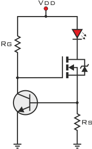
Im 99% sure its linear im a small transistor a mosfet and 2 resistor, i have seen a few people use the same type of driver and it works very well.
 
I just realized how the lines on the graph work.

Im 99% sure its linear im a small transistor a mosfet and 2 resistor, i have seen a few people use the same type of driver and it works very well.

Well make sure you size the resistor correctly for the wattage and get a low tolerance one to stop current wander .
 
I got a 100w 0.01ohm unfortunately the wattage going through it is 112W but its not going to be powered on for long anyway, I also have a 25C temp cutout for the mosfet, as the temperature of the mosfet rises so does the forward voltage drop which makes the current rise, I=Vds/R
 
I got a 100w 0.01ohm unfortunately the wattage going through it is 112W but its not going to be powered on for long anyway, I also have a 25C temp cutout for the mosfet, as the temperature of the mosfet rises so does the forward voltage drop which makes the current rise, I=Vds/R

What ?!?

I don't know if you said anywhere what your LD's current is, but assuming it's roughly 40A (IRs are usually close to 1A / 1W output), then that's 40A running over your 0.01 ohm resistor.

P = I^2 x R = 40^2 x 0.01 = 1600 X 0.01 = 16W

Where are you getting 112W from?
 
Based on 40A Setup

If you are using the circuit RHD posted the link to then the resistor you need is 0.0175 Ohms for 40A so power would be -

P = I^2 x R = 40^2 x 0.0175 = 1600 X 0.0175 = 28W

Mosfet Power dissipation =

Eg - 5 volt source , 2 volts over the diode at 40A , 0.7 volts over sense resistor and then 2.3 volts over the mosfet .

R = V/I = 2.3V/40A = 0.0575 Ohms .

P = I^2 x R = 40^2 x 0.0575 = 1600 X 0.0575 = 92W

Total power of circuit = 5*40 = 200W , 40W optical , 160W heat . ( Heat = 28W in resistor , 40W ish in diode , 92W in Mosfet , + 40W optical = 200W input as above )

Eff is around %20 based on input to optical over whole system


------------------------

That 0.01 ohm resistor you plan to use in the same circuit will cause a current to flow of 70A though that diode and it wont like it ...

P = I^2 x R = 70^2 x 0.0575 = 4900 X 0.01 = 49W

Mosfet = ( same 5V supply )

R = V/I = 2.3V/70A = 0.0328 Ohms

P = I^2 x R = 70^2 x 0.0328 = 4900 X 0.0328 = 160.72W
 
Last edited:
OK after reading and learning some more, I'm getting confused and I want to ask some questions, sorry for my noobness but sometimes the internet is great, and sometimes there is a lot of contradictory information.

Correct me if I am wrong but,
to work out the value of the sensing resistor(Rs) I need 2 things
1.Forward Voltage drop of the diode in the mosfet.
2.The current I want.

The diode is Between Drain to Source right?
so to work out the voltage drop of the diode I need this graph?
28veej5.jpg


So using a transistor at 7V and the mosfet at 25oC and the current at 40A the Forward voltage drop of the diode is about 0.37V?

LED_driving_and_controlling_methods_14.png


I feel so stupid as this is basic stuff :(
 
Last edited:
No worries ,

The internal diode inside the mosfet plays no part in the circuit , its formed anti-parallel when the drain/source junction is made

All you need to mainly worry about is the resistor that sets the current .

As above for 40A you need 0.0175 Ohm resistor ,

The sense resistor is worked out as 0.7V ( transistor base/emitter drop ) devided by the current needed .

0.7V/40A = 0.0175 Ohms .

Voltage wise , there will be 0.7V over the sense resistor , around 2 volts over the laser diode and what's left will be over the mosfet , in the example I gave for a 5 volt supply there will be around 2.3 volts over the mosfet .

You have to remember the mosfet is being used as a variable resistor to control the current .

I can draw the circuit out with the basic relevant voltages on , resistor value if you like , I just need to know the supply voltage you intend to use and the current you would like to run the diode at and then I can work out power dissipation in mosfet and the resistor .
 
Last edited:
Excellent work here, Twirly (ionlaser555)!

If he has already grabbed that 10mOhm resistor I recommend running a second one in series for 0.02 Ohms (~35A). Better to be a bit conservative anyway.

Oh, and 92W into a mosfet is nothing to scoff at, plan your thermal management!


Back
Top