
Welcome to Laser Pointer Forums - discuss green laser pointers, blue laser pointers, and all types of lasers
How to Register on LPF | LPF Donations

Navigation
Install the app
How to install the app on iOS
Follow along with the video below to see how to install our site as a web app on your home screen.
Note: This feature may not be available in some browsers.
More options
You are using an out of date browser. It may not display this or other websites correctly.
You should upgrade or use an alternative browser.
You should upgrade or use an alternative browser.
test load
- Thread starter dtucker21
- Start date


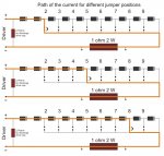
@ bobhaha: I just select how much diodes i have in serie in the circuit with the jumper, from 2 to 10 ..... here is the schematic

The other resistor is just for be sure that the capacitor at the end of the driver is discharged, when you take it away and attach the real LD ..... it don't influence too much the reading, approximatively 3 mA at max ...... and the clips are for connect the DMM more easy, or the scope.
I also thought to add a pair of GE diodes for the 0,4V step with another jumper, but then done nothing, cause it's almost impossible to find GE diodes that hold an ampere ..... at human prices, at least
do i need just 1 amp diodes?
Last edited:
daguin
0
- Joined
- Mar 29, 2008
- Messages
- 15,989
- Points
- 113
i have tried searching
Keep trying. Try different ways to say what you are looking for. LEARN how to do it yourself.
This is basically a DIY type of forum.
If you do not care about learning: If all you want is a working violet laser, you can buy them from Chinese sellers for less than what you paid for in parts from that website you went to.
Come here for HELP NOT service
Peace,
dave
HIMNL9
0
- Joined
- May 26, 2009
- Messages
- 5,318
- Points
- 0
We're speaking about a test load for laser diodes, that usually are working in less than 1 ampere , so the diodes are enough.
Only if you plan to use it with laser diodes that need to regulate the driver over 1 ampere, you may need to use bigger diodes, but i doubt that, actually, is the case")
Only if you plan to use it with laser diodes that need to regulate the driver over 1 ampere, you may need to use bigger diodes, but i doubt that, actually, is the case
We're speaking about a test load for laser diodes, that usually are working in less than 1 ampere , so the diodes are enough.
Only if you plan to use it with laser diodes that need to regulate the driver over 1 ampere, you may need to use bigger diodes, but i doubt that, actually, is the case
if i buy a 6 amp diode would i only need 1??/ for the blu laser
- Joined
- Sep 20, 2008
- Messages
- 17,646
- Points
- 113
If you are truly not capable of understanding the simple instructions
posted by the members above...
Then I would suggest that you buy a laser already built and
functioning...
(Me smells a troll... I could be wrong)
Jerry
posted by the members above...
Then I would suggest that you buy a laser already built and
functioning...
(Me smells a troll... I could be wrong)
Jerry
bobhaha
0
- Joined
- May 31, 2009
- Messages
- 3,239
- Points
- 63
@ bobhaha: I just select how much diodes i have in serie in the circuit with the jumper, from 2 to 10 ..... here is the schematic
The other resistor is just for be sure that the capacitor at the end of the driver is discharged, when you take it away and attach the real LD ..... it don't influence too much the reading, approximatively 3 mA at max ...... and the clips are for connect the DMM more easy, or the scope.
I also thought to add a pair of GE diodes for the 0,4V step with another jumper, but then done nothing, cause it's almost impossible to find GE diodes that hold an ampere ..... at human prices, at least
WOW this is awesome.. I'm gonna try build something like that.. but one problem... if all the diodes are in series what stops it from enabeling all 10? like if you put a jumper at #3.. why wouldn't it just flow both #3 jumper and all 10 diodes.. only reason i can think of is.. it takes the path with less resistance.. but that violates an energy law stating energy flows through out the total ciruit despite its paths resistance. Am I wrong in assuming that the picture is incorrect? i have a feeling there should be a jumper at #10
HIMNL9
0
- Joined
- May 26, 2009
- Messages
- 5,318
- Points
- 0
@ bobhaha: no, if you look at the schematic, you can see why ..... if you put the jumper, as example, in position 2, the first 2 diodes are in the circuit, but all the rest are shorted from the common line of the jumper connector (practically, they are bypassed to the resistor) ..... and the same for all the other positions, cause, ofcourse, if you put a piece of wire in parallel with the diode, the diode become bypassed, and this is valid for one as the same as for all them, depend from the position of the jumper (hope the draws are more clear of my bad english ") )
)

The diodes above the jumper are part of the circuit, the diodes below the jumper are just short-circuited, and in this way, bypassed, as they are just not there ..... and ofcourse, without the jumper, all 10 are in circuit.
............................
@ dtucker21: you are confusing current and voltage dropout.
The number of the diodes in the circuit, are not for change the current that the circuit can hold (also cause for that, they had to be in parallel, not in serie) ..... they are used for simulate the voltage dropout of a real laser diode, cause in this way, you can set the driver more accurately.
Each diode cause a dropout of 0,7 / 0,75V, so, for set a driver for use it with a red LD (LD = Laser Diode), that have usually 2,5 to 3 V or similar of FV (FV = Forward Voltage, the working voltage of the diode), you use 4 diodes, that cause a dropout of 4x0,7=2,8V, that is similar to the one of the real LD ..... this cause set up the current for a driver, is better when you use a dummy load that have similar characteristics to the real final load.
..............................
I don't know, really ..... but i ensure you that i have talked personally with a lot of peoples that don't understand the difference between current and voltage, so i give him doubt benefit, for now
)The diodes above the jumper are part of the circuit, the diodes below the jumper are just short-circuited, and in this way, bypassed, as they are just not there ..... and ofcourse, without the jumper, all 10 are in circuit.
............................
@ dtucker21: you are confusing current and voltage dropout.
The number of the diodes in the circuit, are not for change the current that the circuit can hold (also cause for that, they had to be in parallel, not in serie) ..... they are used for simulate the voltage dropout of a real laser diode, cause in this way, you can set the driver more accurately.
Each diode cause a dropout of 0,7 / 0,75V, so, for set a driver for use it with a red LD (LD = Laser Diode), that have usually 2,5 to 3 V or similar of FV (FV = Forward Voltage, the working voltage of the diode), you use 4 diodes, that cause a dropout of 4x0,7=2,8V, that is similar to the one of the real LD ..... this cause set up the current for a driver, is better when you use a dummy load that have similar characteristics to the real final load.
..............................
(Me smells a troll... I could be wrong)
Jerry
I don't know, really ..... but i ensure you that i have talked personally with a lot of peoples that don't understand the difference between current and voltage, so i give him doubt benefit, for now
Attachments
bobhaha
0
- Joined
- May 31, 2009
- Messages
- 3,239
- Points
- 63
ok I totally understand now.. thats very cool! this will come in handy for the lasers I'm thinking of building next!
- Joined
- Apr 9, 2008
- Messages
- 374
- Points
- 28
This is great!! Thanks HIMNL9!!
I have been following several threads to build my own test load which would allow me to to test different drivers, for reds, blurays and higher currents as those used by the 445nm LDs but using just one unit.
There is several threads that are covering the same subject. As someone mentioned, they all are coming together, and from what I have read, yours is the best approach but each contribute very nicely.
I have not checked the calculations with the 1N5402 diodes and I will later, but posted the concept at: http://laserpointerforums.com/f51/dummy-load-high-current-2a-test-load-52372.html#post736135
I didn't want you to think that was taking your idea to another thread but to bring everyone together to possibly one design that serves everyone.
Thanks!
Last edited:
- Joined
- May 28, 2008
- Messages
- 101
- Points
- 18
HIMNL9
0
- Joined
- May 26, 2009
- Messages
- 5,318
- Points
- 0
Cause the jumper have virtually zero resistance, like a piece of wire, and the current always flow in the less resistance path (basical electronic laws) ..... if there was a resistor, in place of the jumper, the current flow in both the branches, proportionally, but if one of the brabches (the jumper) have resistance = zero, all the current flows there.
- Joined
- Aug 30, 2008
- Messages
- 260
- Points
- 18
Hey HIMNL9
thats a awesome little set up there. Simple yet very practical. Nice work!
If you dont mind, im gonna copy it, lol, will come in handy.
Cheers
Dave
thats a awesome little set up there. Simple yet very practical. Nice work!
If you dont mind, im gonna copy it, lol, will come in handy.
Cheers
Dave
HIMNL9
0
- Joined
- May 26, 2009
- Messages
- 5,318
- Points
- 0
LOL, anyone is free to copy anything i post in a public place, no problems at all, for me 
qumefox
0
- Joined
- Mar 26, 2010
- Messages
- 3,221
- Points
- 63
Cause the jumper have virtually zero resistance, like a piece of wire, and the current always flow in the less resistance path (basical electronic laws) ..... if there was a resistor, in place of the jumper, the current flow in both the branches, proportionally, but if one of the brabches (the jumper) have resistance = zero, all the current flows there.
If they wanted to, there's nothing to stop anyone from adding a jumper at 10 as well. But as you said, it wouldn't change how the circuit behaves any.