Welcome to Laser Pointer Forums - discuss green laser pointers, blue laser pointers, and all types of lasers

LPF Donation via Stripe | LPF Donation - Other Methods

Links below open in new window

ArcticMyst Security by Avery

Computer PSU to power LDs?

Joined
Nov 18, 2009
Messages
253
Points
0
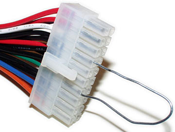
I've seen a few threads and photos on LPF that indicate some people have "converted" an old computer Power Supply Unit to provide power for their DIY laser experiments and lab lasers. I've also seen such a thing explained on the Instructables site.

I'm very interested in seeing if I could "convert" such a PSU into some sort of "lab" power source. I mean, they come complete with a power switch, and cooling fans, too!

If I understand things, those PSU's provide 12v, 5v, and 3.x volts, right? So depending on how much power is needed for a particular application, you'd just plug into the correct jack (or hook up the proper wires, etc)....

BUT, wouldn't you still need either:

1. A driver to provide the proper current (and limit its max) for the LD? Like a RKCSTR, Microdrive, etc? Although these are typically used because of their small size to fit inside a flashlight host, and are attached directly to the LD, correct?

or

2. A further means to "dial in" the proper mA of power going directly to the LD? Almost like a dimmer switch of some sort. This would be a separate component attached or associated with the PSU, not attached to the LD.... Thus allowing a more "universal" source of power without worrying about a specific driver for a specific LD.

How would #2 be accomplished? I mean, as a quick test to see if a harvested LD is even working, couldn't you hook it up (w/ alligator clips) to this variable power source, and start on the low end (25mA) and slowly up the level to 100, 200, etc mA until you see a dot/beam?

You'd probably have to have a built-in meter as well, which indicated exactly how much current is going to the LD.

Isn't this the premise for those store-bought, separate laser power supplies that are used for HeNe lab lasers, etc?? I've seen photos of them which digitally indicate the mA being used to power the particular laser.

I guess even for a "stand-alone" adjustable power source, you'd still basically be using a driver, but it wouldn't be inside a host, but maybe integrated into the PSU box, or as a separate module.

On a side-note (question), are the drivers (like RKCSTR, etc) laid out and built on a small circuit board only because they need to be small to fit inside hosts? Could the same type of driver be built "larger" to fit inside its own case? Kind of like modular laser components (lens holders, mirror holders, etc), where each piece secures onto an aluminum rail system?

Hopefully this all makes some sort of sense. I'm new to electronics so I don't really know the correct terminology. Let me know if I need to clarify or re-word anything.

Thank you for reading, and for any input you can provide.


Joined
Jun 19, 2009
Messages
2,710
Points
0
The Rckstr is a tiny version of the DDL driver, which uses an LM317T, so yes, it can be built bigger, there's a large thread about it here, made by it's creator, Daedal, and there's some info about it on rog8811.com.
 
Joined
May 4, 2009
Messages
2,238
Points
83
You kinda lost me there allitle bit in that long post :yabbem:

I have a converted PSU and it appears to be fine for driving LD's. I had it for a while driving a 1W c-mount straight off of it and it worked fine, up until one day when i turned on the PSU when the 12V rail was connected and sent the little guy to diode heaven :(
 
Joined
May 4, 2009
Messages
2,238
Points
83
I wonder if these types of converted PSU's could be good for driving big 10~20W diodes :thinking: I would sure like that :D
 
Joined
Aug 15, 2009
Messages
1,443
Points
48
First: those small drivers need a filtered power supply like batteries, a switched power supply for those may give noise to the diode too. And, these driver provide a few 100's of milliamps, so you can only power small diodes, making a large computer power supply reduntant.

If you want a high current output, get a proper driver. Laser diodes >= 1 watt require more than an amp, not something a small driver can give. Diode bars need tens of amps, go figure. I'm building a driver for my 20W diode bar and I already build a 2ch 2A laser diode driver. I can make a custom driver or help you with your own design if you want.
 
Joined
Feb 21, 2008
Messages
1,056
Points
0
You can use a computer power supply made into a bench PSU for all sorts of testing.
The 3.3V output can be used to test green modules, and measure their input current. PHR's can be tested by hooking the diode and regulator to the 12V output. Consider it a stable replacement for batteries. A current regulator is still required for the laser diode. This gives you a second project that you can make. Build a current regulator for testing LD's on the bench. I made one that can go up to 3A. The max current is set by a resistor that connects by two binding posts and a pot lets me vary the current from zero to the max set by the resistor. I use this for testing and graphing LD's. It also has jacks to plug in a DMM set on mV, to display the diode current 1mV=1mA. A third very useful item is the variable voltage power supply. With one of these, you can determine how low voltage can drop before your driver drops out of regulation and laser power begins to drop. It's nice to know the minimum operating voltages of your lasers. I built my variable voltage supply with a battery charger sized 15V transformer from junk, bridge rectifier, filter caps, LM338 regulator (7A if well heatsinked) pot, and resistor. Simple very useful item for the laser and electronics workbench.
 
Joined
Nov 18, 2009
Messages
253
Points
0
The Rckstr is a tiny version of the DDL driver, which uses an LM317T, so yes, it can be built bigger, there's a large thread about it here, made by it's creator, Daedal, and there's some info about it on rog8811.com.
Yes, I think I may have already seen that. Thank you.

I have a converted PSU and it appears to be fine for driving LD's. I had it for a while driving a 1W c-mount straight off of it and it worked fine...
Wow. 1W? I'm nowherre near that kind of power yet.

First: those small drivers need a filtered power supply like batteries, a switched power supply for those may give noise to the diode too. And, these driver provide a few 100's of milliamps, so you can only power small diodes, making a large computer power supply reduntant.

If you want a high current output, get a proper driver. Laser diodes >= 1 watt require more than an amp, not something a small driver can give. Diode bars need tens of amps, go figure. I can make a custom driver or help you with your own design if you want.
I'm not interested in 1W lasers (yet). I'm just interested in an "easy" power connection to hook up LDs to see if they even work at all. Before putting them into hosts.

Thank you for the offer of your assistance. I appreciate it.

You can use a computer power supply made into a bench PSU for all sorts of testing.
The 3.3V output can be used to test green modules, and measure their input current. PHR's can be tested by hooking the diode and regulator to the 12V output. Consider it a stable replacement for batteries. A current regulator is still required for the laser diode. This gives you a second project that you can make. Build a current regulator for testing LD's on the bench. I made one that can go up to 3A. The max current is set by a resistor that connects by two binding posts and a pot lets me vary the current from zero to the max set by the resistor. I use this for testing and graphing LD's. It also has jacks to plug in a DMM set on mV, to display the diode current 1mV=1mA. A third very useful item is the variable voltage power supply. With one of these, you can determine how low voltage can drop before your driver drops out of regulation and laser power begins to drop. It's nice to know the minimum operating voltages of your lasers. I built my variable voltage supply with a battery charger sized 15V transformer from junk, bridge rectifier, filter caps, LM338 regulator (7A if well heatsinked) pot, and resistor. Simple very useful item for the laser and electronics workbench.
Ah, adfter reading your post, I think this is what I'm talking about wanting:

1. A power supply that can be used in place of batteries, so I can quickly and easily test laser diodes as I harvest them. I'm guessing a computer's PSU will suffice for this?

2. A current regulator ("driver") that can be adjustable. Being able to hook it up to a DMM would be very beneficial I would think.

I'm not too knowledgable on the variable voltage supply you're talking about. I'm a newbie to electronics and understanding resistors and capacitors (etc). But would this take the place of the PSU, or be used in addition to it?


Thanks for everyone's help on this!

FYI: I was able to salvage a PSU from an old Dell PowerEdge 1300 server. Here's the specs on the PSU sticker:

Dell
Model: NPS-300GB B REV: 03

INPUT 100-120V~/ 10.0A, 200-240V~/ 5.0A
50-60Hz Autorange
OUTPUT +5V === / 35.0A, -5V === / 0.3A,
330W MAX. +12V === / 14.0A, -12V === / 0.3A,
+5VFP === / 1.2A, +3.3V === / 18.0A,
Max combined power on +5V and +3.3V OUTPUT is 230W.

I have no idea what all of that means right now.

It seems that there are 6 power connections that are labeled:

P1: largest group of wires (24 total), connected to motherboard. Has red, white, black, blue, brown, gray, and orange wires.

P2: medium sized group of wires (9 total). Has red, yellow, black, and blue/white stripe wires. Then there's an adapter on the end which splits this run into 2 sets of 2 unlabeled power connectors for what I'd call "standard" power for 4 drives.

P3: "standard" power connector (4 wires total). Red, yellow, and 2 black wires. Also goes into P4.

P5: "standard" power connector (4 wires total). Red, yellow, and 2 black wires. Also goes into P6 (Floppy drive power).

All the wire sizes are the same, except for the wires leadinbg to P6, which are thinner.

That's all I know for now. This electronics stuff is new to me, so I'm going rather slowly with it.

If anyone can offer further info/tips/suggestions, I'm all ears! Thank you.
 
Joined
Feb 21, 2008
Messages
1,056
Points
0
1)Yes, the computer PSU can be made into a bench PSU by adding binding posts on the case so you get a nice unit.

2)This is a bench laser driver (current regulator) with variable output. This is powered off the bench PSU above, and regulates the current for the LD you are testing.

A variable voltage supply is a very easy project to make once you get started in electronics. It is a very useful item, as a knob on it sets the output voltage.

If you open the power supply that you have salvaged, you'll see that all of the output wires that feed the computer come from one part of the PCB. The black ones are ground or negative. Measuring with a DMM between a black wire and the different colored ones will tell you which color has what voltage. You will find +12V, -12V, +5V, -5V, and 3.3V outputs that can be run to binding posts. For more info, google for computer psu mods or psu from computer. I think that there are instructables at instructables.com for doing the computer psu. Attached are two photos of PSU's.

In this photo, the top and bottom are computer PSU's whose wires have been shortened and run to binding posts. Very handy and useful. The middle unit is the variable voltage power supply.

attachment.php


The next photo is a 0-3A variable current regulator, the DMM to its' left is used to read the mA's drawn by the LD under test.

attachment.php
 

Attachments

  • Dec2609D200 001 [2].jpg
    Dec2609D200 001 [2].jpg
    143.5 KB · Views: 3,044
  • Dec2609D200 002 [1].jpg
    Dec2609D200 002 [1].jpg
    265.4 KB · Views: 2,491
Joined
Nov 18, 2009
Messages
253
Points
0
OK, so I've had a look-see into the PSU. I must say, it's very interesting. I never knew there were heat sinks inside a PSU. I did know that there had to be a fuse, and some sort of converter (since the input is AC and the output is DC).

Here's a side view of it:
1661-dell-psu-02-right-side.jpg


And the other side:
1662-dell-psu-04-left-side.jpg


Are these "giant" capacitors (200v)?
1663-dell-psu-06-right-detail.jpg


Here's a detail of all the wires:
1664-dell-psu-09-output-detail.jpg

What is all that white stuff? Some sort of glue to "stiffen" it all so the wires don't pull out easily?

I understand about the binding posts on the outside of the unit, and shortening the wires inside for it. But I don't think there's room for any of that inside mine, so I think I'll construct a separate "unit".... Do I want to cut off all the wires right before the plastic "plugs" (P1, P2, etc)?

I'll take a look at the Instructable that I saved the other day, too.
 
Last edited:
Joined
Feb 21, 2008
Messages
1,056
Points
0
How this thing works (simplified) is the AC goes in, a bridge and the big 200V caps rectify and filter. The DC (at around 170V) then goes through circuitry that based on a high frequency oscillator by a PWM type chip and power mosfets delivers pulses to a ferrite transformer, whose secondary windings produce the lower voltages. These lower voltages are recified by large fast diodes on one of the heatsinks. There is feedback, so voltage can be regulated on the outputs.

The white gunk is usually some type of silicone. Fortunately, it seems to come off easily when I scrap one of these for the useful electronic components inside.

As far as cutting the wires off, just make them long enough to reach where you need them to go, oe else coil up the excess inside the unit that you build. Some of the units have a "power good" or "power check" output that needs at least the draw of an LED in order for the supply to not go into a standby mode. If the supply won't run by itself not connected to a PC, you will need to find this odd wire (could be blue or purple on some models) and get a LED and resistor between it and ground so there is some mA's of draw to keep the supply on. The result will be a good stable power supply for your test bench.
 
Joined
Nov 18, 2009
Messages
253
Points
0
Since my PSU didn't come with an on/off switch, I was researching how to keep it on. I came across SuicideKing's post from a different thread:

If your power connector has 24 pins, jump pin #16 (it's always the one with the green wire) to any black wire (ground). If your power connector has 20 pins, jump pin# 14 (again, it's always the green one) to any ground pin (black wire).

With the respective pins grounded, the power supply can be run stand alone, without a mother board and you can turn it on or off using the mechanical power switch on the back, near the power cord socket.

Most new powersupplies come with both connectors, so you could use the connector that's NOT plugged into your motherboard as a remote on/off swtich, by wiring a switch between the green wired pin and ground (one of the black wired pins).

connector_atx_pinout.GIF

runatx360.jpg
My power connector has the 24 pins, but it's NOTHING like the wire color pictured. SuicideKing says it's always the green wire. But my 24-pin connector has a black wire in pin16. Will this mess me up w/ figuring out what's what? Or will pin16 always be the one I want regardless of wire color? I just don't want to get the wrong one and do something stupid.
 
Joined
Sep 20, 2008
Messages
17,622
Points
113
How about a clear picture of both sides of your connector taken like the
ones you posted above...

Jerry
 
Joined
Dec 29, 2009
Messages
3,136
Points
63
Was it a Dell PSU? :crackup:

Look for a green or grey wire, should be in the spot that your diagram shows. pictures of the actual plug and wires might help.

Dell stuff, for a while, was all proprietary.
 

Benm

0
Joined
Aug 16, 2007
Messages
7,896
Points
113
PC PSU's are hardly a good choice for these things. Often they require some minimal load to function properly, and drving a laser diode is not likely to meet that.

These switchting power supplies are designed to work very welll with the intended loads connected, but sometimes can do strange things ohterwise.. be wary!
 
Joined
Nov 18, 2009
Messages
253
Points
0
How about a clear picture of both sides of your connector taken like the ones you posted above...
Here ya go.

Pins 13-24:
1803-dell-psu-12-pins-13-thru-24.jpg


Pins 01-12:
1804-dell-psu-13-pins-01-thru-12.jpg


In case the photo isn't clear enough, the wire colors are as follows (assuming Dell follows the same pin layout):

01 red
02 black
03 red
04 black
05 orange
06 purple?
07 yellow
08 blue
09 black
10 black
11 blue w/ white stripe
12 blue

13 black
14 blue
15 red
16 brown
17 red
18 red
19 red
20 white
21 black
22 black
23 black
24 gray

Was it a Dell PSU? :crackup:Dell stuff, for a while, was all proprietary.
Why yes, yes it was. It was a Dell PowerEdge 1300 server.


Top