- Joined
- May 9, 2011
- Messages
- 1,228
- Points
- 113
Thanks Jordan!


Follow along with the video below to see how to install our site as a web app on your home screen.
Note: This feature may not be available in some browsers.


If I was going to drive 9 x nubm44's I would regulate the current not the voltage so I would regulate @ 4.5a and make sure there was 42 volts available although it would likely draw closer to 41v @ 4.5a
Typically I run a nubm44 at 4.5a and it will draw about 4.5v however the factory data projector drives at a lower current that's sustainable with active cooling, it also adjusts for demands and compensates for wear over time, that's why we can push them so hard, there is a lot of headroom built in.
Anyway if you regulate current the diodes will draw the voltage they need, so you want your driver to be able to supply it, also laser diodes don't like spikes or noise so you wouldn't want to use just anything, actually a linear would make sense for 9 x nubm44's in series and would be pretty easy to make.
") Why?"
Why?"Recently decided to look into it and found some tests showing a loading voltage surges for 2S and 3S packs can be huge like 20V for 3S packs due to near zero internal resistance.


OK, challenge accepted
E: Anyone know a shortcut for a PCB already made for this regulator for CC?
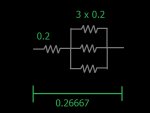
For 4.5a the resistor would be 0.2667 the cap is not needed AFAIK
The input capacitor is a good thing. Mostly it will work without, especially when powered from a battery with short leads and such. But it doesn't do anything bad here either, and can prevent problems with oscillations - just leave it in as long as you have physical space for it.
Also make sure you get the proper resistors. As drawn, the single 0.2 one drops 0.9 volts at 4.5 amp, dissipating 1.8 watts. You'd need a 2 watt resistor, but make sure you do not use wire wound resistors, their inductive nature causes problems. So make sure it's a film type.
There are more ways to get to about 2.66 ohms though. As the whole combination dissipates a whopping 1.25 volts x 4.5 amps or 5.6 watts you have some choices to make. One would be to use 0.4 watt metal film resistors. 14 3.9 ohm resistors in paralel would give you the value needed, and be within their power rating as well.