I have a TEC based LPM detector that I would like calibrated.
I am in Adelaide Australia. Anyone local with a calibrated LPM that could help me out please?
Any help much appreciated.
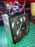
Heatsink - CPU heatsink with fan - surplus from local computer shop - $0
TEC - Custom Thermoelectric TEC - pn 03111-5L31-03CF - $20.00
Krylon UltraFlat Black Paint
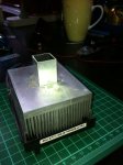
Polished the mounting area for the TEC to a mirror finish
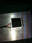
Painted one face of the TEC with black
Glued the TEC to the heatsink with Artic Silver
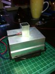
Painted the inside of the aluminium tube with black
Glued the aluminium tube to the heatsink with high grade cyanoacrylate
The aluminium tube has about 1mm clearance all round the TEC
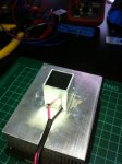
Glued the lead wires to the heat sink for strain relief
Measure mV output direct from the TEC with multimeter (no amp required)
The aluminium tube prevents problems with stray air currents, direct light and also provides a great way to mount various attachments for measuring mounted and unmounted diodes.
Haven't needed to use the fan at all but only measuring up to about 350mW so far. The fan will help when measuring higher powers for longer duty cycles as the airflow will help maintain a more stable heatsink temp.
All works like a charm with high repeatability and stability but now I need calibration to correlate mV to mW.
I am in Adelaide Australia. Anyone local with a calibrated LPM that could help me out please?
Any help much appreciated.
Heatsink - CPU heatsink with fan - surplus from local computer shop - $0
TEC - Custom Thermoelectric TEC - pn 03111-5L31-03CF - $20.00
Krylon UltraFlat Black Paint
Polished the mounting area for the TEC to a mirror finish
Painted one face of the TEC with black
Glued the TEC to the heatsink with Artic Silver
Painted the inside of the aluminium tube with black
Glued the aluminium tube to the heatsink with high grade cyanoacrylate
The aluminium tube has about 1mm clearance all round the TEC
Glued the lead wires to the heat sink for strain relief
Measure mV output direct from the TEC with multimeter (no amp required)
The aluminium tube prevents problems with stray air currents, direct light and also provides a great way to mount various attachments for measuring mounted and unmounted diodes.
Haven't needed to use the fan at all but only measuring up to about 350mW so far. The fan will help when measuring higher powers for longer duty cycles as the airflow will help maintain a more stable heatsink temp.
All works like a charm with high repeatability and stability but now I need calibration to correlate mV to mW.