Welcome to Laser Pointer Forums - discuss green laser pointers, blue laser pointers, and all types of lasers

LPF Donation via Stripe | LPF Donation - Other Methods

Links below open in new window

ArcticMyst Security by Avery

First scanner advice needed, right step into scanners?


Joined
Nov 7, 2008
Messages
5,725
Points
0
Not personally, but out of the various systems I have used I haven't found a galvo block yet that has a different thread.. it's kind of standard.

I should add the disclaimer that the Chinese are notorious for having no manufacturing standards (even among products form the same manufacturer) and their machining equipment can be "out-of-spec" shall we say, so variation, while rare, isn't unheard of.

If yours is different from this it would be the first galvo block that I've seen that is, but I wouldn't necessarily be surprised.
 
Last edited:

XysteR

0
Joined
Apr 26, 2009
Messages
49
Points
0
In my readings i'm sure i've seen M 4 too but i couldn't find where i found it to verify. Must be right then surely.

I have placed my Flashback 3 XE order :D All i need to do now is make the casing. Upto now its cost £850 for the Flashback 3, DT25's, Green analog laser, 27mm X 47mm X 10mm plate.


***** I'm soooo itching to put this lot together! *****
 
Last edited:

Things

0
Joined
May 1, 2007
Messages
7,517
Points
0
Yes M3 or M4.

I wont be here to reply for a few days, I am down picking up a few laser goodies from Dave @ LSP :D
 

XysteR

0
Joined
Apr 26, 2009
Messages
49
Points
0
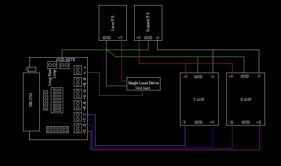
Hey guys, just wanted to try and help clear something up a bit. On XYsteR's amp, the pin has the "sideways T" label really should be left disconnected all together. ILDA pin 25 (GND or Ground) should be attached directly to the scanner power supply, in particular to the screw labelled "COM". This will prevent a ground loop.

The wiring for the laser can also be a bit wierd. Ideally, you would only connect "modulation +" line and leave the other disconnected, and attach ILDA pin 25 to the 0V rail of the laser power supply. A laser that has the driver and power supply built together, or if the modulation input is isolated for protection (seems the Laserwave lasers have this built in) will need to have both "modulation + and modulation -" attached. However, the "modulation -" should be attached to ilda pin 25. The R-, G- and B- are really for a laser that has a differential front end, which most of them do not. Some DAC's can handle having these lines (R-, G-, B-) grounded, then you can use them if you have to. If your DAC is able to handle having the minus lines grounded, and you have a breakout board, then you can just turn on switches 3, 4 and 5 to ground the minus lines on the breakout board.

Thanks for the info. I think i need to spend the next few days getting an understanding and clarifying how to wire this lot up correctly.

Yes M3 or M4.

I wont be here to reply for a few days, I am down picking up a few laser goodies from Dave @ LSP :D

Laser goodies! :D

Well, i'm officially in the Pangolin club! Pangolin Flashback 3 XE bought, paid for and on its way to me. I should get it in a couple of days, my aluminium plate is on its way too.
 
Last edited:
Joined
Apr 2, 2009
Messages
356
Points
0
I am getting parts together for my own scanner too. I am going with sound card DAC for my first one then I will upgrade to a better DAC when I have the money. For my Galvo's I have a few different ones to choose from that are in my price range. I am looking to spend about $300 shipped for them. I want a set that I won't get bored with right off the bat. Here is a few I have all heard good things about.

$250 shipped -- DT-25 from -- DZE

$250 shipped -- laser galvo scanning 30Kpps -- laser galvo scanning 30Kpps for laser show light - eBay (item 120445056114 end time Aug-05-09 11:04:43 PDT)

$260 shipped -- Laser Galvo Scanning 33Kpps -- ILDA Breakout Broad and Laser Galvo Scanning 33Kpps - eBay (item 120426709891 end time Aug-25-09 12:17:29 PDT)

Does anyone have any suggestions on which one I should go with?
 
Joined
Nov 7, 2008
Messages
5,725
Points
0
^I'd stick to a set that we know has a proven reputation. The other sets look decent, but the only one that I would be 100% comfortable recommending would be the DT-25s..
 

XysteR

0
Joined
Apr 26, 2009
Messages
49
Points
0
Ok, here we go. I get a better understanding to 'see' things, i learn better that way.

This is what i think to be correct for wiring up my DT 25's and Laser-wave analog green laser to an ILDA port. I will be connecting my Flashback 3 XE DAC to the ILDA port.

Is this correct?

**** Snipped image, its been updated later in the thread ****
 
Last edited:
Joined
Nov 7, 2008
Messages
5,725
Points
0
Perfect! That's precisely right. I like the diagram.. never seen it drawn out quite so simply, which makes it very easy to understand.
 

XysteR

0
Joined
Apr 26, 2009
Messages
49
Points
0
Perfect! That's precisely right. I like the diagram.. never seen it drawn out quite so simply, which makes it very easy to understand.

Simple is the only way forward for me lol I can see now how the FB3 gets grounded to the Scanner PSU as quoted by 'Pangolin Bill' in the DT-25 manual. I'm assuming 'COM' is common ground?

I was wondering, when i attach the AC in earth cable to the chassis of my casing is the DC common ground isolated from it? or are both common ground and AC earth be connected to the chassis?
 
Joined
Nov 7, 2008
Messages
5,725
Points
0
Ground is ground, regardless of AC or DC or voltage. Just as long as you mean AC earth, not AC neutral.. I've seen them get confused before with disastrous consequences. Also, you're correct about COM.
 

XysteR

0
Joined
Apr 26, 2009
Messages
49
Points
0
Yes AC earth (yellow & green here in the UK)

When i see all of these common ground connections is it not easier to just put a single screw somewhere in my optic aluminium plate and just connect the grounds all in one place then have one wire running from this point to pin25 on the ILDA port?
 

XysteR

0
Joined
Apr 26, 2009
Messages
49
Points
0
that's how it's done..

Ah haaaa kerching. Penny just dropped! lol


One more thing that confuzzles me.. The manual for my analog lasers modulation wires are labelled + and - yet that is marked as negative but goes to ground? If something is marked negative in AC, as you stated, the last thing you want to do is connect it to ground.
 
Last edited:

XysteR

0
Joined
Apr 26, 2009
Messages
49
Points
0
Right, now i'm confused again.. I've just been looking at the following image in detail. Particularly the grey wire from the 'Single Laser Driver' it doesn't go to any of the colours?

Picture is property of DZE from DZE hope he doesn't mind me using it. The grey wire that goes to +i i assume this is modulation and will be the same as my Yellow + modulation wire on my green laser? Does mine go to +G or +i Hmmm?

It seems if i had RGB then i'd connect to +R +G +B but why do i connect to +i for a single colour?

Looking at the ILDA pinouts the only thing i can see with +i is intensity/blanking. I wonder if +i contains all of the signals from RGB so you don't get missing colours from single green a show, it'll pass the Red and Blue signal to green? I'm thinking if a show is designed to show red green and blue then it'd not look very good with only the green areas alone being activated with blank gaps where the missing red and blue should be. Hmm i'm tired, this is baking my nOOdle lol

Breakoutboard_SingleLaser_Setup.jpg
 
Last edited:


Top