Welcome to Laser Pointer Forums - discuss green laser pointers, blue laser pointers, and all types of lasers

LPF Donation via Stripe | LPF Donation - Other Methods

Links below open in new window

ArcticMyst Security by Avery

Which part to replace after battery inversion?

Joined
Mar 7, 2015
Messages
5
Points
0
Hi all,

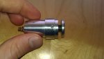
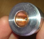
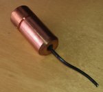
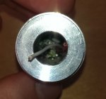
I have been using my Sci-Fi 501B 445nm 1475mw laser for a while. However, in a flurry of excitement I inserted the batteries in the wrong way. Now, there is no guarantee on the product so I am wondering which parts I must replace? Is it only the driver or is the diode also dead? :confused:


Joined
May 14, 2013
Messages
3,438
Points
0
It is usually the driver, that would be an M140 build so there is a good chance it's using an X-drive, an X-drive will last a few seconds and burns out the driver and not the diode. Does the driver look like this? https://sites.google.com/site/dtrlpf/home/flexdrives/x-drive If it's using this driver then it will be soldered directly to the pins on the diode, look at that chip with 8 connections with a magnifying glass, there may be a burn mark in one corner of that chip if it's burned out. If you have the proper equipment and tools you can test both the driver and diode, but don't attempt this if you don't know what your doing or you will need to replace both of them.

Alan
 
Joined
Mar 7, 2015
Messages
5
Points
0
It is usually the driver, that would be an M140 build so there is a good chance it's using an X-drive, an X-drive will last a few seconds and burns out the driver and not the diode. Does the driver look like this? https://sites.google.com/site/dtrlpf/home/flexdrives/x-drive If it's using this driver then it will be soldered directly to the pins on the diode, look at that chip with 8 connections with a magnifying glass, there may be a burn mark in one corner of that chip if it's burned out. If you have the proper equipment and tools you can test both the driver and diode, but don't attempt this if you don't know what your doing or you will need to replace both of them.

Alan

Thanks for the reply Alan,

I will first have to remove the connection board which is glued into place correct?
There is also a small hole in the heatsink with a tiny hex socket (I assume) in it. I am not sure what to remove in order to gain access to the inside.
Furthermore, I lack specific equipment for this job! Only have a 'normal' soldering iron.

See pictures:
 

Attachments

  • IMAG1585.jpg
    IMAG1585.jpg
    102.9 KB · Views: 115
  • IMAG1584.jpg
    IMAG1584.jpg
    90.4 KB · Views: 102
Last edited:
Joined
May 14, 2013
Messages
3,438
Points
0
Thanks for the reply Alan,

I will first have to remove the connection board which is glued into place correct?
There is also a small hole in the heatsink with a tiny hex socket (I assume) in it. I am not sure what to remove in order to gain access to the inside.
Furthermore, I lack specific equipment for this job! Only have a 'normal' soldering iron.

See pictures:

No you shouldn't need to remove the battery contact board. You should just need to find the correct size Allen wrench that fits the set screw in that tiny hole in the heat sink, then just unscrew it and the module should slide out, it will have wires that are soldered to wires from the battery contact board.

Alan
 
Joined
Mar 7, 2015
Messages
5
Points
0
No you shouldn't need to remove the battery contact board. You should just need to find the correct size Allen wrench that fits the set screw in that tiny hole in the heat sink, then just unscrew it and the module should slide out, it will have wires that are soldered to wires from the battery contact board.

Alan

Ok, so I was able to remove it but there is no movement whatsoever. Pulling with force, tapping the heatsink all didn't work. The copper piece is really stuck inside. I also removed the focusing mechanism and spring, now you can see how tight the copper is on the aluminium.
 

Attachments

  • IMAG1586.jpg
    IMAG1586.jpg
    123.5 KB · Views: 114
Last edited:
Joined
May 14, 2013
Messages
3,438
Points
0
Ok, so I was able to remove it but there is no movement whatsoever. Pulling with force, tapping the heatsink all didn't work. The copper piece is really stuck inside. I also removed the focusing mechanism and spring, now you can see how tight the copper is on the aluminium.

This isn't good, it could be glued in place with thermal adhesive. Not a good practice in my opinion because it's mostly permanent, it might not be possible to get it apart. Now I don't know what to suggest. Sorry.

Alan
 
Joined
Mar 7, 2015
Messages
5
Points
0
This isn't good, it could be glued in place with thermal adhesive. Not a good practice in my opinion because it's mostly permanent, it might not be possible to get it apart. Now I don't know what to suggest. Sorry.

Alan

Ah, that's annoying :yabbmad:

Thank you anway for your help. I will try contact the maker of the laser again and see if he will reply this time.
 
Joined
Mar 30, 2012
Messages
1,321
Points
0
The module is not glued. It is being pressed into the heatsink so it will not move and adding a set screw on the side for securing it even better.

You will need to take the driver out. Then use a press or something to take it out. I would just leave it there. And just replace the driver.

I was a bit busy so could not respond.

I would suggest getting a new driver. I can send one for free if needed.

:beer:
 
Joined
Mar 7, 2015
Messages
5
Points
0
This isn't good, it could be glued in place with thermal adhesive. Not a good practice in my opinion because it's mostly permanent, it might not be possible to get it apart. Now I don't know what to suggest. Sorry.

Alan

Oh my... I tried once again and it finally came loose but I ripped the wires loose!!
There was no other way of getting it out sadly. Any ideas on what to do now?
Edit: Thejoker301 and I are working on it together.
 

Attachments

  • IMAG1589.jpg
    IMAG1589.jpg
    117.3 KB · Views: 119
  • IMAG1587.jpg
    IMAG1587.jpg
    119.9 KB · Views: 119
Last edited:


Top