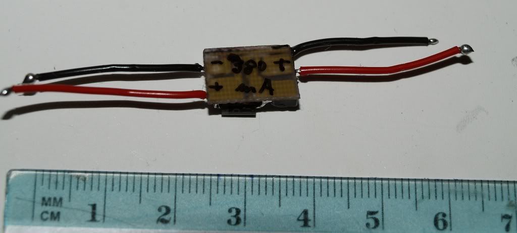
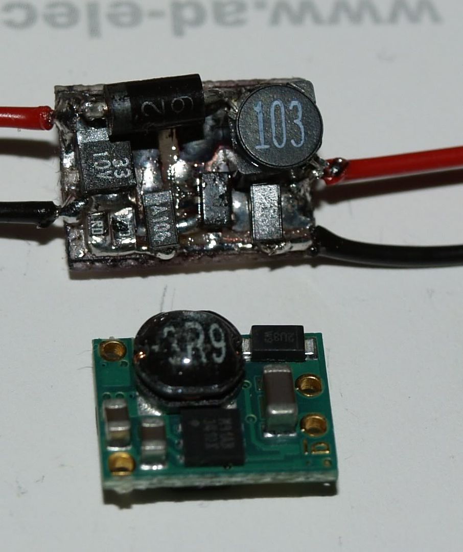
A buck/boost driver is a style of driving topology. just like linear (LM317 for example) is a style of driver etc.
The homemade aspect of it involves making the actual PCB itself and soldering crap onto it. Also.. you'd only be using buck or boost, not buck and boost. buck for a step down DC-DC convertion, boost for step up.
Ill post pics when I make the new board for this build, I dont have any more that arent inside hosts.
EDIT:
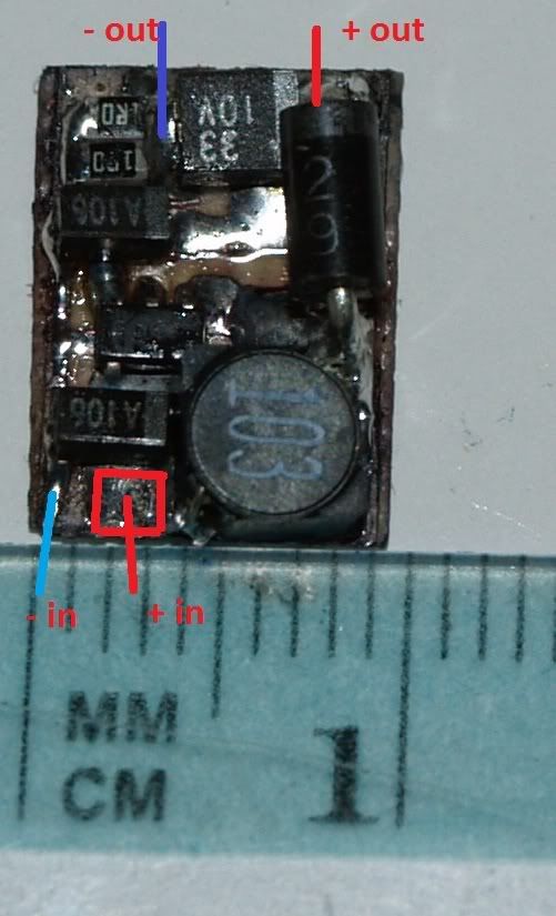
Since on the topic, for this build, like any, I try out different layouts and better designs, just to see if I can get the driver as relaible as possible without taking too much room.
This screenshot is my first layout for this build, but I think I will revise it should I be able to make the layout smaller or change the driver.
So here is a quick screenshot.. I put a TO-220 for size referance.
I doubt this will be the final layout.. I think I can do better.
(as you can see, this thing is too huge compared to most drivers here.. needs to be shrinked... alot)
As much as I would have liked to aviod it, I will probably have to do a double layer design, rather then single.
[pic]
Ill probably make this one anyway, just as a prototype so I can know that the final design itself works properly (Ive been having some issues with inductor saturation in early lashups, I found the issues and now Im worrying about an actual layout.). then I can worry about downsizing.


")