Welcome to Laser Pointer Forums - discuss green laser pointers, blue laser pointers, and all types of lasers

Buy Site Supporter Role (remove some ads) | LPF Donations

Links below open in new window

FrozenGate by Avery

vacuum fluorescent indicator tubes

it's not that bad once you find yourself armed with patience and desoldering wick...
couple of years back i made a 12vdc-600vdc 500W converter on the very same perfboard. It draws 50+ amps, so i had to use strips of copper foil here and there, but if laid out correctly, almost any prototype design <100MHz should work ok.


Oh I didn't mean to imply there is any issue with the material itself, just that the construction process can be psychosis inducing, lol.
 
Yes, it can be nerve-racking up to a certain point. then it's copy/pasting--counter,decoder,counter,decoder,counter, oops a solder bridge, etc.
I spent some extra time on the front end circuit and keeping all connections tight with generous grounding. It has enough gain to amplify less than 20mV in 50 ohms at 150MHz to couple of volts needed by the 74AC nands and flipflops that follow.
I thought it would oscillate wildly, but the stability of those jellybean BFR93's never ceases to amaze me.
Also, the same cmos chip that draws, say, 10uA at 1 kHz sucks 50-100mA at 150Mc and warms up noticeably chrgin/discharging all those capacitances in its cmos structures...Plus, what looks like a super high impedance cmos input at LF and DC now wants a low impedance source to provide the 3-5 v swing across 10pf of input capacitance.
I would have done this with balanced ECL gates, but those are not readily available and cost a lot more...
 
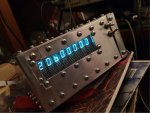
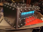
i decided to throw this in a box. all i used in the box building process was some Al sheeting and L angles, scissors and a drill...not even a ruler, as you can probably tell....and 120 M3 screws.
Apart from the numerous glaring aesthetic omissions, the box turned out pretty squarish without any visible torsion and rhomboid properties. All i really opted for was a RF-tight enclosure to block the huge quantity of RF garbage the counter makes from being radiated outside, either directly or thru the power wires. The 74AC/AHC chips inside are rather 'nervous' bastards spewing harmonics well beyond 1.5GHz.There are many multiples of 10MHz/the ref clock/ and also the frequency being measured, scaled down, gated, counted, whatever...not to mention the 500kHz 5V buck regulator. put in perspective, all of that combined can knock out fm reception within 5-10 meter radius.
When boxed up, though, nothing comes out on the specan screen even with the preamp on. This is aslo the reason why there are 120 screws and a wire mesh in front of the vfds.
power is supplied thru a feed-thru capacitor on the rear panel.
The only source of RF leakage is the BNC 10Mc ref out socket on the rear side. A 50-ohm terminator or copper tape can seal it off.
the front panel has a 1x-10x switch and a selector switch to add or subtract a hard-coded offset /intermediate freq/.

it now counts to 200MHz @ <10mV, well above the max clock freq specs of the 74AHC74 FF in the front-end
 

Attachments

  • IMG_1088.JPG
    IMG_1088.JPG
    133 KB · Views: 71
  • IMG_1089.JPG
    IMG_1089.JPG
    131.6 KB · Views: 63
Very nice! Having something boxed up and self contained firmly, no matter how "ugly" the box is always more appealing than having it spread out across a table top. It is unfortunate that we often have to rely on table-spread work, but enclosures are expensive and hard to make.
 
the box reminds me of the riveted turret of a tank...
having this particular thing spread out across the tabletop would render it useless because of its noisy nature. i intend to use it as a frequency display in a sw receiver so it has to be silent.
i can buy locally die cast boxes of various sizes, but they are all painted, which means that the lid would be 'floating', electromagnetically speaking.
I got a big one and i'll stick a VFO with a huge silvered inductor inside and use the above counter with it.


Back
Top