Welcome to Laser Pointer Forums - discuss green laser pointers, blue laser pointers, and all types of lasers

Buy Site Supporter Role (remove some ads) | LPF Donations

Links below open in new window

FrozenGate by Avery

Using a DC/DC converter to power the laser

for sure u could keep the bulky 47uf on the board. the ceramic one should remain on th leads for best high freq suppression, though.
regarding eff - what inductors are u using? i have only tested it at a fixed Vout of 2.74V and variable Vin and it remained fairly constant over the operating range, deteriorating a bit around the lower margin of Vin


phenol said:
for sure u could keep the bulky 47uf on the board. the ceramic one should remain on th leads for best high freq suppression, though.
Oh, absolutelly.. I understand that by now (thanks to you). All my LDs have ceramic SMD caps directly on the leads now..

But as long as the power on spike can be absorbed by the tantalums directly on board, i'm happy.. In that case i have a working and reliable driver circuit..


regarding eff - what inductors are u using?  i have only tested it at a fixed Vout of 2.74V and variable Vin and it remained fairly constant over the operating range, deteriorating a bit around the lower margin of Vin
I'm using the exact CoilCraft inductors specified in the datasheet..

When i lower the input voltage my efficiency goes down, like expected, but for some reason, the efficiency is better, when the output voltage is higher, regardless of the input voltage..

Right now i'm at almost 70% efficiency at 2.838V and 213mA on the LD, which is not that bad.. What percentage did you measure?


BTW: The square chip red has been running at this power for more than an hour now.. I'm monitoring the output power with a solar cell directly in front of it, attached to a multimeter, measuring milliamps.. The output has remained constant this entire time..

This is also the longest time i ever left a laser on continuously..


EDIT: Oh, and you were right about the resistor producing that smoke.. Now that i disconnected everything after powering the red for an hour and a half, i looked at the circuit, and noticed a black spot in the middle of the sense resistor. Obviously it got so hot, that it vapourised it's coating. I should replace it...


Anyway, looks like the circuit is now suitable for driving a laser. Many years ago i bought a <1mW laser pointer (my first laser ever), that has place for two AAA batteries.. I'll use this circuit to revive it and turn it into a powerfull 16x burner.. I never thought that one would work again one day.. :)
 
Anyone know what a good through hole substitute for the BAT54CT small signal schottky diode would be?

I would like to try the bootstrap circuit for 2 Ni-MH cell operation...
 
IgorT said:
Anyone know what a good through hole substitute for the BAT54CT small signal schottky diode would be?

I would like to try the bootstrap circuit for 2 Ni-MH cell operation...
you could use 2x1n5817 if you have the space. btw, the only part that doesnt correspond to the bom in the design example for you now is the catch diode, which could account for the lower than expected eff. the values that i measured are ~72-74%
 
the circuit we have been playing with requires 1 IC, 1 diode, 2 inductors, 2 resistors and a few capacitors.
all SMD.
take a look at page 24 on this datasheet for the circuit and component values. http://cache.national.com/ds/LM/LM3410.pdf

the IC and inductors are available as free samples
and you will also need to make yourself a PCB
this is (edit:) NOT for the electronics novice. although it isn't that hard to put together considering its all SMD
 
phenol said:
you could use 2x1n5817 if you have the space.
I think i can squeeze them in.. Shouldn't be to hard to do, even without making new PCBs.. Thanks!


btw, the only part that doesnt correspond to the bom in the design example for you now is the catch diode, which could account for the lower than expected eff. the values that i measured are ~72-74%
Yeah, even my PCB is almost exactly the same as the evaluation board, only smaller.. I did make some traces thinner, but also shorter at the same time, so i thought it would even out..

Maybe i should try different catch diode, but my engineer said this one should be perfect.. I don't know.. I also measured the temperatures of every component on my board after running it for an hour and a half, and my IR thermometer showed only 30°C max on the IC, coils and the diode..


Still 67.5% efficiency is not that bad, compared to the LM317 circuit, especially if you consider that this one can run from only two Ni-MHs.


I'm gonna try to revive the old laser pointer today, maybe add two chokes on the output, just to feel better about the LD. I have enough coils now...
 
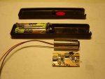
Here's a pic of my circuit, next to an AixiZ module, and the old pointer enclosure, it is all going in..
It came out very small, and fits into the old pointer perfectly...


I set the current to 250mA by using a 1 Ohm and a 4 Ohm resistors in parallel. The 4 Ohm is two 2 Ohm in series.


On the output of the circuit you can see the two added 47uF tantalums for the power on spike, and there are two ceramic SMD caps inside the module. The only thing missing are the two axial chokes between the circuit and the LD. I'll put them in now.


Since the circuit is very thin, i'll be able to put another one on top, for the momentary push button and a switch.


This old laser pointer was my first laser, which i killed 8 years ago, when i tried to see if i can push it.. I'm very excited about finally reviving it. It used to be <1mW and now it's gonna be at least 150 times as powerfull..

I can't wait to finish it! :)
 

Attachments

  • Old_pointer_revival.JPG
    Old_pointer_revival.JPG
    25.3 KB · Views: 138
toked323 said:
so what are all the parts needed to make 1 of these board, like components wise

I don't know where to buy SMD components in small numbers, so i just looked for the caps and resistors in old DVD burners, unsoldered them and measured the caps on my multimeter.


As Woop said, the IC and inductors are available as free samples, but you can only order the IC samples if you have a proper e-mail address (gmail or similiar isn't good), if it looks like a business address, even better.

They ship the samples very fast, without asking any questions.. If you have a gmail-like address, you have to pay for shipping.


CoilCraft can be a little more conservative, but if you say you're a student and keep the sample order small (6 pieces), they send the inductors..
You do have to send an e-mail, explaining what the "student project" is, who your proffesor is and give them his phone number (they don't actually call it).


Then you just etch a board, and put everything together.. Everything except the IC is easy to solder by hand.. For the IC you would need SMD solder paste.. Phenol managed to solder it by hand and so did i, but i wouldn't recommend trying, unless you have LOTS of experience with soldering.
 
Everything except the IC is easy to solder by hand.. For the IC you would need SMD solder paste.. Phenol managed to solder it by hand and so did i, but i wouldn't recommend trying, unless you have LOTS of experience with soldering.
i second that; the slightest flicker of your hand would mess up the chip and the tiny pads on the pcb and end it up in the garbage can...unless you gain access to the sot-23 version, which they do not ship as samples.
 
IgorT said:
Here's a pic of my circuit, next to an AixiZ module, and the old pointer enclosure, it is all going in..
It came out very small, and fits into the old pointer perfectly...


I set the current to 250mA by using a 1 Ohm and a 4 Ohm resistors in parallel. The 4 Ohm is two 2 Ohm in series.


On the output of the circuit you can see the two added 47uF tantalums for the power on spike, and there are two ceramic SMD caps inside the module. The only thing missing are the two axial chokes between the circuit and the LD. I'll put them in now.


Since the circuit is very thin, i'll be able to put another one on top, for the momentary push button and a switch.


This old laser pointer was my first laser, which i killed 8 years ago, when i tried to see if i can push it.. I'm very excited about finally reviving it. It used to be <1mW and now it's gonna be at least 150 times as powerfull..

I can't wait to finish it! :)

you are probably being a bit paranoid with all those caps, AND 2 inductors. did you see the blueray thing that chimo made, using a 1xAA phone charger? the output on those things are totally unregulated and yet it hasn't killed the laser. i reckon the voltage (or rather accompanied current spikes) would be within the pulsed diode's capabilities.
BUT, better safe than sorry i guess. LD's are not cheap
 
woop said:
you are probably being a bit paranoid with all those caps, AND 2 inductors. did you see the blueray thing that chimo made, using a 1xAA phone charger? the output on those things are totally unregulated and yet it hasn't killed the laser. i reckon the voltage (or rather accompanied current spikes) would be within the pulsed diode's capabilities.
BUT, better safe than sorry i guess. LD's are not cheap

Yes, i am being a bit too cautious, but since i have these chokes on hand anyway, there's no reason not to put them in..

I did see chimos thread, and also discussed it with him there... He mentioned what i was thinking about just a day before, but couldn't find anything in Sam's FAQ about - these LDs being pulsed for writing anyway, so maybe this current ripple doesn't really matter all that much..


I think chimo got very lucky with that circuit, that it puts out just the right current for a blue ray.. If i can use the 3410 for them, it would be great!
But you can be sure, that chokes will be in there as well, especially since i allready killed the two from the first group buy.. :) They are VERY sensitive.


I got most of the 16x LDs for free, but my supply is very limited. The open can costs me almost twice as much as it costs someone in the US.. So i'm gonna keep being too cautious. Like you said, better safe than sorry.

Two axial chokes cost almost nothing.. An LD on the other hand is a hard thing for me to replace...
 
as it turns out SEPIConverters can work just fine, and even better, with 1 inductor. to be more precise-with one core and two magnetically coupled identical windings on it. this way, if for a given ripple current the required value is L, using two separate coils, the new value using 2 coils on 1 core is L/2.=> less wire, lower resistive losses, smaller boardspace.
i tried it and it works, winding a bifilar inductor on a small toroid core. there is more info here:
http://www.coilcraft.com/pdfs/doc639_Selecting_SEPIC_Inductors.pdf
 
phenol said:
as it turns out SEPIConverters can work just fine, and even better, with 1 inductor. to be more precise-with one core and two magnetically coupled identical windings on it. this way, if for a given ripple current the required value is L, using two separate coils, the new value using 2 coils on 1 core is L/2.=> less wire, lower resistive losses, smaller boardspace.
i tried it and it works, winding a bifilar inductor on a small toroid core. there is more info here:
http://www.coilcraft.com/pdfs/doc639_Selecting_SEPIC_Inductors.pdf

I've seen that. It's mentioned on their first page. It could make the boards very tiny.

I'm not capable of designing such a board myself tho.. It would take me WAY too long and it probably wouldn't look good in the end. Besides, i'm happy with it, as it is.. If i need it smaller, i have lots of free space on the board, so i can squeeze everything together a bit.. But i just checked, and it fits nicelly into my tiny door opener remote enclosure as well, leaving space for two AAA Ni-MHs..


I put the zener on the circuit output in reverse, for overvoltage protection, if the LD or a choke should fail.

I'm also going to put those two additional diodes and a capacitor on it for the bootstrap version. I just need to cut the trace between pins 1 and 2. Don't have to make new circuits...


I'm gonna finish this laser today..
 
My old laser pointer lives again! It works from only two AAA cells perfectly! I'm gonna like this one very much....


Something weird happened tho.. Untill today i had a 0.91 Ohm resistor in it, and the current was 213mA with any load that i put on, regardless of the output voltage, just like expected..

For 250mA i calculated i need 0.8 Ohms, so i put a 1 Ohm and 4 Ohm in parallel..  Then i put everything into the old laser pointer, and put my multimeter between the LD and the circuit output. I wanted to make sure that the current really is 250mA..

Then i powered it on, but the meter only showed 200mA. This would be the correct current for a 1 Ohm resistor, so i thought there is something wrong with the two 2 Ohm, that i put in series, to act as a 4 Ohm.. So i took them out, and the current dropped to 150mA with 1 Ohm Rsense...

This would mean, that Vfb is 150mV instead of 200mV, like it was yesturday...

How the hell is this possible? I thought maybe the batteries are not capable of putting out enough current, so i put it on the PSU with 4.2V, like it was untill now, but i got the same result..


I had to use the 1 Ohm and 2 Ohm in parallel, to get 243mA through the LD.
It now works nicelly, and can regulate the current from only two AAA cells, but i don't understand, how the feedback voltage could change so much from one day to the other..

And my setup is the same as it was during all the previous tests. I didn't change anything. I didn't put those chokes in, nothing...


I just don't get it..

Oh, and i doublechecked with another multimeter.. They both show the same current.
 
Oh, when i was calculating efficiency yesturday, i was relying on the voltage and current displayed on the PSU, and measured on the load...
Now i figured out my PSU shows 20mA more current, than is actually flowing to my circuit (need to calibrate it)..

My actual efficiency is 74.6%! So at least this part is great! (And the part, where it gives me current regulation from only two AAA cells of course :))


Actually, everything is great. I just don't understand, how Vfb could change to 150mV.. This is outside of the datasheet's specifications..


Back
Top